16
A2A
SIMULATIONS :::
ACCU-SIM V35B BONANZA
FLYING INTO THE FUTURE
FOR SIMULATION USE ONLY
(nose up) incidence when the elevator is neutral that suf-
ficient “decalage” (also known as “horizontal dihedral”) is
created relative to the wing’s angle of incidence. The non-
horizontal ruddervators, when at neutral, are less efficient
in creating sufficient decalage than a conventional horizon-
tal stabilizer/elevator and therefore must be set at a greater
positive incidence. Being at greater incidence puts each of
the ruddervators under a greater positive aerodynamic load
at all times and thereby creates greater induced drag (drag
which occurs whenever an aeroplane’s wing and/or tail sur-
faces positively redirect the oncoming airflow) than are cre-
ated by conventional horizontal surfaces.
Additionally, in Bonanza, the right ruddervator is offset a
few degrees more to the right than the left ruddervator to
counter P- factor, also called “asymmetric blade effect” and
“asymmetric disc effect” (relocation of a spinning propel-
ler’s centre of thrust when the propeller disc is at a positive
angle of attack [Alpha] which in a right hand- turning pro-
peller exerts a left yawing moment on the aircraft and vice
versa). To reiterate, because each ruddervator is offset from
vertical, they must be set at a greater degree to the right to
counter P- effect than a conventional single fin/rudder sur-
face would need to be to exert the same force.
■
Form/pressure drag
In order to preserve pitch and yaw stability as well as to
grant efficient control displacement forces, the wetted area
(the area exposed to the oncoming air) of the ruddervators
must be roughly equal to that of conventional tail surfaces.
Accordingly, each of the “V” surfaces must be larger both
in chord and/or span than that of equally- effective conven-
tional tail surfaces. Accordingly, the ruddervators’ wetted
area produces form/pressure drag equal to or greater than
that produced by conventional tail surfaces.
■
Yaw/Roll Instability or “Dutch Roll”
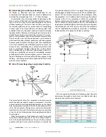
Properly applied, a small amount of dihedral creates a stabi-
lising force in a wing or horizontal tail surface so that when
it is displaced in the roll axis by turbulence, a gust of wind
or after the aircraft is deliberately banked, it will tend to
return to level flight. However, when tail surfaces are radi-
cally offset upward (as in a “V”- tail,) a very strong dihedral
force is created at the rear of the aeroplane.
Some aircraft are designed with some amount of horizon-
tal tail surface dihedral to increase roll- axis stability. Less
commonly, some aircraft are designed with some negative
(downward) horizontal tail surface dihedral, called “anhe-
dral” or “cathedral,” to decrease what is considered to be an
excess of roll- axis stability. It is understood that extreme
dihedral (or extreme sweepback) tends to instigate a con-
dition called “Dutch Roll,” a series of out- of- phase turns
in which an aeroplane tends to roll from side to side whilst
also yawing in the opposite direction of the roll and not
remaining at or returning to level flight without engaging
a yaw and/or pitch damper, an auto pilot and/or the pilot’s
corrective control input.
Accordingly, Bonanza’s 30º-
33º ruddervators tend to
cause Dutch Roll at the rear of the aeroplane, which has
been reported to cause both yaw and pitch “wandering” and
pitch “seeking” at cruise airspeeds.
ADVANTAGES:
■
Airspeed?
Beech’s claim that a “V”- tail design sufficiently reduces
drag so that it increases the aircraft’s airspeed as com-
pared to the same aircraft with a conventional tail has been
shown not to be so. If any such advantage exists at all, it is
de minimus at best. Even Beech (which some have claimed
has not always been known to have played entirely fairly
with regard to its aeroplanes’ published airspeed specifi-
cations) lists the cruising airspeeds of the last “V”- tail
Bonanza, V35B, as being the same (172 knots) as an equally
powered F33A (a conventionally- tailed Bonanza.)
■
Appearance
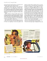
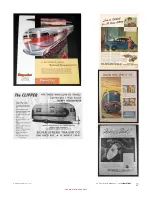
Many would agree that the undisputed advantage that a
“V”- tail has over a conventional tail is its appearance. It is
certainly eye- catching and unless the truth of the matter is
known to the observer, a “V”- tail appears to be cleaner and
more efficient. Beechcraft apparently heavily relied upon
this erroneous assumption and affirmatively added to it for
decades in order to generate Bonanza sales. As stated before,
despite its exotic appearance and appeal, the “V”- tail actu-
ally does not improve aircraft performance in any measur-
able amount as compared to a conventional tail.
A RARELY ADOPTED TAIL DESIGN
There are so many inefficiencies and control rigging com-
plications involved with the “V”- tail design that it is not a
surprise that it has been so rarely used.
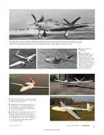
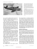
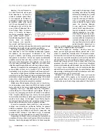
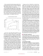
Whilst at least 15 jet engine-
powered military aero-
planes and at least one helicopter incorporating a “V”- tail
are known to exist at this time (2018,) the only piston-
engine fighter known to have been built with a “V”- tail is
the experimental Bell P- 63A- 8 “Kingcobra”. This one- off
aeroplane was a test bed to find out if such a tail configu-
ration might increase the top airspeed of the already quite
fast P- 63D “Kingcobra”. Powered by an Allison V- 1710- 109
engine producing 1,425 hp and with a top airspeed of 437
mph at 30,000 feet (on par with P- 51 “Mustang’ and P- 47
“Thunderbolt”), P- 63A- 8 was already flying nearly as fast
as a propeller- driven fighter could be made to fly. This
P- 63D was so modified and was designated P- 63A- 8. It
broke up during diving tests before it could be determined
whether the substitution of the “V”- tail produced less drag
than the conventional tail surface arrangement and accord-
ingly produced any increase of airspeed. It is not reported
whether the “V”- tail was the cause of P- 63A- 8’s in- flight
breakup but speculation thereof abounds. Experiments with
“V”- tails were not made thereafter.
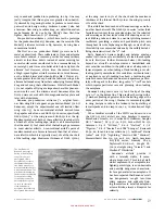
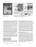
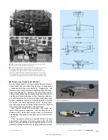
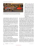
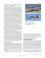
In 1944 Beech built an interesting experimental Model 18
“Twin Beech” designated A- 19 on the airframe of a USAAF
A- 10 “Wichita.” A large “V”- tail was substituted for the
conventional tail surfaces. Extensive stability and control
Summary of Contents for BONANZA ACCU-SIM V35B
Page 1: ...A2ASIMULATIONS BONANZA ACCU SIM V35B BONANZA ...
Page 3: ...A2ASIMULATIONS BONANZA ACCU SIM V35B BONANZA ...
Page 5: ...www a2asimulations com ACCU SIM V35B BONANZA A2ASIMULATIONS 5 FOR SIMULATION USE ONLY ...
Page 27: ...www a2asimulations com ACCU SIM V35B BONANZA A2ASIMULATIONS 27 FOR SIMULATION USE ONLY ...
Page 58: ......
Page 68: ...68 A2ASIMULATIONS ACCU SIM V35B BONANZA www a2asimulations com FOR SIMULATION USE ONLY ...
Page 112: ......


