www.a2asimulations.com
ACCU-SIM V35B BONANZA
:::
A2A
SIMULATIONS
97
FOR SIMULATION USE ONLY
FUEL REQUIRED FOR FLIGHT
It is the pilot’s responsibility to ascertain that the fuel
quantity indicators are functioning and maintaining a rea-
sonable degree of accuracy, and to be certain of ample fuel
for a flight. Takeoff is prohibited if the fuel quantity indi-
cators do not indicate above the yellow arc. An inaccurate
indicator could give an erroneous indication of fuel quan-
tity. A minimum of 13 gallons of fuel is required in each tank
before takeoff. The caps should be removed and fuel quan-
tity checked to give the pilot an indication of fuel on board.
The airplane must be approximately level for visual inspec-
tion of the tank. If it is not certain that at least 13 gallons are
in each tank, fuel shall be added so that the amount of fuel
will be not less than 13 gallons per tank at takeoff. Plan for
an ample margin of fuel for any flight.
ELECTRICAL SYSTEM
The system circuitry is the single-wire, ground-return
type, with the airplane structure used as the ground return.
The battery ON-OFF switch, the alternator ON-OFF switch
and the magneto/start switch are located on the left sub-
panel. The circuit breaker panel is located on the right sub-
panel and contains circuit breakers for the various electrical
systems. Some switch-type circuit breakers are located on
the left subpanel.
BATTERY
A 15.5-ampere-hour, 24-volt battery is located on the
right forward side of the firewall. Battery servicing pro-
cedures are described in the HANDLING, SERVICING, AND
MAINTENANCE Section.
ALTERNATOR
The airplane is equipped with a 50-, 60- or 100-ampere,
gear-driven alternator. The alternators are designed to
maintain approximately 50-, 60- or 100-amperes output
respectively at 1700 rpm, to provide airplane electrical
power.
A transistorized electronic voltage regulator adjusts alter-
nator output to the required electrical load, including battery
recharge. Charging or discharging of the battery is indicated
by the ammeter. A zero reading, which is normal for cruis-
ing flight, indicates that the battery is fully charged and that
alternator output has been adjusted by the voltage regu-
late to balance the load of the electrical equipment in use.
The alternator-out warning light, located on the instrument
panel, can be tested with the TEST WARN LIGHTS switch
adjacent to the warning lights.
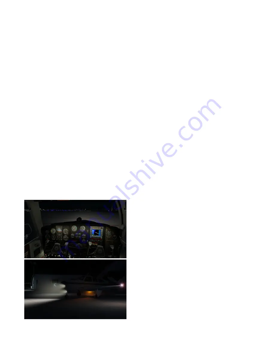
INTERIOR LIGHTING
Lighting for the instrument panel is controlled by thumb-
rotated, disc-type rheostats, located on the pilot’s sub-
panel to the left of the control column. The first rheostat
is labeled RADIO and ENG and controls the lighting of the
avionics panel and the multiple readout engine instrument.
The second rheostat, labeled INST, is optional and controls
the lighting for the flight instruments and the instrument
pressure gage.
On the lower subpanel are two more lighting rheostats.
The first, labeled SUB, controls the intensity of the complete
subpanel lighting. The second rheostat is labeled FLOOD and
controls the glare shield lighting, which illuminates the full
upper panel.
The cabin dome light is operated by an ON-OFF switch
adjacent to the light. The optional reading lights above
the rear seats have individual switches at the lights. The
optional map light has a press-type switch on the control
wheel. The OAT, map, and compass lights are controlled by
a push-on, push-off switch located adjacent to the OAT or
on the control wheel.
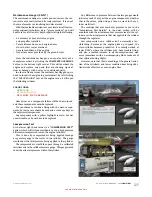
EXTERIOR LIGHTING
The switches for all of the exterior lights are located on the
pilot’s left subpanel. Each switch is a circuit-breaker-type
switch, which will open if it becomes overloaded or shorted.
The exterior lights consist of navigation lights on the
wing tips and tail cone, a landing light in the fuselage nose
section, and a taxi light attached to the nose strut. The
landing light can be used for approach and taxiing. Use the
landing light for approach and the taxi light for taxiing. For
longer battery and lamp life, use the landing light and the
taxi light sparingly; avoid prolonged operation which could
cause overheating during ground maneuvering.
NOTE
Particularly at night, reflections from anti-collision lights on clouds, dense
haze or dust can produce optical· illusions and intense vertigo. Such lights,
when installed, should be turned off before entering an overcast; their use
may not be advisable under instrument or limited VFR conditions.
Summary of Contents for BONANZA ACCU-SIM V35B
Page 1: ...A2ASIMULATIONS BONANZA ACCU SIM V35B BONANZA ...
Page 3: ...A2ASIMULATIONS BONANZA ACCU SIM V35B BONANZA ...
Page 5: ...www a2asimulations com ACCU SIM V35B BONANZA A2ASIMULATIONS 5 FOR SIMULATION USE ONLY ...
Page 27: ...www a2asimulations com ACCU SIM V35B BONANZA A2ASIMULATIONS 27 FOR SIMULATION USE ONLY ...
Page 58: ......
Page 68: ...68 A2ASIMULATIONS ACCU SIM V35B BONANZA www a2asimulations com FOR SIMULATION USE ONLY ...
Page 112: ......


