background image

Manuale di installazione, Uso e Manutenzione  - 

Installation, Use and Maintenance Manual

pag. 16

• Il sifone deve infine essere dotato di tappo per la pulizia nella parte

bassa o deve comunque permettere un veloce smontaggio per la pulizia
periodica

• Il percorso del tubo di scarico condensa deve avere sempre un pen-

denza verso l'esterno, deve inoltre risultare il più breve possibile e con il
minor numero possibile di curve

• Assicurarsi sempre che il tubo per il deflusso della condensa non solle-

citi l'attacco di scarico dell'unità, prevedendone, se necessario, un
opportuno staffaggio.

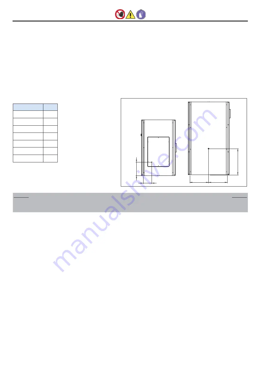
• Il raccordo di scarico condensa si trova sulla parte inferiore 

dell’unità, come evidenziato nella figura sotto

• La posizione standard dello scarico, per modelli orizzontali, è esplicita-

ta nella tabella seguente.

• The siphon must finally have a cap for cleaning the lower part or must

however allow quick disassembly for periodical cleaning

• The route f the condensate drain pipe must always slope towards the out-

side. It must also be as short as possible and with the least number of
bends

• Always make sure that the condensate flow pipe does not stress the unit

drain connection, envisioning appropriate bracketing if necessary.

• The condensate drain is located in the underside of the unit, as highigh-

ted in the figure below

• The standard position of the drain is made clear in the following table.

7.7.2 Batteria di post riscaldamento ad acqua BCR

• L'eventuale batteria di post-riscaldamento ad acqua BCR è fornita di

attacchi "maschio" con filettatura GAS.

• Le operazioni di serraggio vanno effettuate con cautela per evitare dan-

neggiamenti dei collettori in rame della batteria.

• Il percorso dei tubi deve essere studiato in modo da non creare ostaco-

li in caso di estrazione della batteria dell'unità.

• Entrata e uscita acqua devono essere tali da consentire lo scambio ter-

mico in controcorrente: seguire quindi le indicazioni delle targhette
ENTRATA  ACQUA e USCITA  ACQUA.

• Prevedere una valvola di sfiato in alto ed una di scarico in basso.
• Staffare adeguatamente i tubi all'esterno della unità per evitare di scari-

carne il peso sulla batteria.

• A collegamento effettuato spingere bene la guarnizione esterna in

gomma contro il pannello per evitare trafilamenti d'aria.

• La coibentazione deve giungere a filo pannello per evitare pericolo di

scottature.

• Prevedere, a livello di regolazione, l'intercettazione della batteria lato

tubi a ventilatore spento per evitare surriscaldamento dell'interno della
centrale con possibile danneggiamento di alcuni componenti.

• Prevedere valvole di intercettazione per isolare la batteria dal resto dei

circuito in caso di manutenzione straordinaria.

• Prevedere dispositivo antigelo.
• Nel caso di installazione in zone con climi particolarmente freddi, svuo-

tare l'impianto in previsione di lunghi periodi di ferma dell'impianto.

7.7.2 Water post-heating coil BCR                            

• Possible water heating coil is provided with gas threaded male connec-

tion.

• Fixing shall be carried out carefully without any damage on coil headers
• Pipeline shall be designed so that coil can be easily removed.
• Follow instructions “Water IN” and “Water OUT” to connect water pipes

properly.

• Coil headers or pipeline shall be provided with both upper air valve and

lower water discharge valve.

• Coil headers shall not be used as support for pipes; pipes shall be sup-

ported by proper fixing system.

• After connecting headers, press the external rubber gasket against the

coil panel to avoid air leakage.

• Heat insulation of the pipes shall be up to panel wall to avoid burns.
• (questa sarebbe da togliere, è contorta e pertinente solo se c’è un riscal-

datore di tipo elettrico).

• Provide pipeline with shut-off water valves in the event of unscheduled

maintenance.

• Add antifreeze in the water circuit; empty water circuit in the event of unit

not running for long time at very cold weather condition.

=

=

A

355

228*

CFR+ 40

RIMUOVENDO LE SEI VITI DI FISSAGGIO, È POSSIBILE RIMUOVERE IL COPER-
CHIO INFERIORE, LA VASCHETTA RACCOGLI CONDENSA ED IL
RECUPERATORE

CFR+ 40

REMOVING THE SIX FIXING SCREWS, IT IS POSSIBLE TO ROTATE THE BOTTOM
COVER, CONDENSATE DRIP TRAY AND THE HEAT EXCHANGER

Modello / 

Model

A (mm)

75 N

700

100 N

700

150 N

780

200 N

780

320 N

860

400 N

860

500 N

860

CFR+ 40 N

CFR+ 75/500 N

7 - INSTALLAZIONE E MESSA IN SERVIZIO  

7 - INSTALLATION AND START UP 

Summary of Contents for A CFR+ 40

Page 1: ...INFORMAZIONI TECNICHE A_CFR A_CFRE 40 500 Unit di recupero di calore orizzontale con scambiatore statico in controcorrente di alluminio A_CFR 40 75 100 200 320 A_CFRE 40 75 100 200 320 400 500...

Page 2: ......

Page 3: ...M MCUE MCUEM 23 8 2 Schemi elettrici Serie CFR 26 8 3 Schema Elettrico Sistema Bioxigen 38 9 CONTROLLI PRIMA DELL AVVIAMENTO 39 10 MANUTENZIONE ORDINARIA 39 10 1 Avvertenze 39 10 2 Controlli mensili 3...

Page 4: ...and as a consequence must be kept carefully and must ALWAYS accom pany the appliance even if transferred to other owners or users or transferred to another plant If damaged or lost request ano ther c...

Page 5: ...doors for accessing the internal parts of the appliance without first having switched off the master switch of the system vietato disperdere abbandonare o lasciare alla portata di bambini il materiale...

Page 6: ...tta di identificazione che riporta A Marchio del Costruttore B Indirizzo del Costruttore C Modello unit D Matricola unit E Tensione n fasi frequenza di alimentazione F Corrente assorbita massima G Cod...

Page 7: ...istenza elettrica di post riscaldamento integrata BER Batteria interna di post riscaldamento ad acqua BCR Sezione con batteria ad acqua promiscua SBFR Sezione con batteria espansione diretta SBED Filt...

Page 8: ...mits C 5 45 C 5 95 Condizioni di temperatura umidit limite esterne con accessorio RMS Outdoor temperature humidity working limits with RMS option C 15 45 C 5 95 Condizioni di temperatura umidit limite...

Page 9: ...ust air Aria di rinnovo Fresh air Lato destro Right side Lato quadro elettrico ed ispezione filtri Electrical board and inspection filters side BCR BER Accessori Options Lato destro Right side BCR BER...

Page 10: ...to aggiuntivo e l accessorio RMS possibile gestire lo sbrina mento del recuperatore Infatti se il pressostato rileva una caduta di pres sione eccessiva dovuta alla brina che ostruisce il recuperatore...

Page 11: ...ch T mm K 2 mm J mm W mm Kg 40 1480 380 800 200 110 210 230 90 70 3 4 1 2 355 500 412 177 90 75 1940 480 990 300 100 310 230 140 210 3 4 1 2 697 500 550 190 140 100 1940 480 990 300 100 310 230 140 26...

Page 12: ...ceiving the goods before unloading all the material delivered must be checked to ascertain the presence of any damage caused during transport Any damage found must be reported to the carrier accepting...

Page 13: ...ormative antinqui namento previste N B L installatore e l utilizzatore nell uso dell unit devono tenere conto e porre rimedio a tutti gli altri tipi di rischio connessi con l impianto Ad esem pio risc...

Page 14: ...o di sostegno sia perfettamente oriz zontale onde permettere il corretto accoppiamento delle varie sezioni Non posizionare l unit in locali in cui siano presenti gas infiammabili sostanze acide aggres...

Page 15: ...ing and fix M8 threaded tie rods as indicated in the figure 2 Position the unit on the tie rods 3 Block the unit by fastening the fixing bolt IMPORTANTE SI FA DIVIETO DI METTERE IN FUNZIONE L UNIT SE...

Page 16: ...esterno della unit per evitare di scari carne il peso sulla batteria A collegamento effettuato spingere bene la guarnizione esterna in gomma contro il pannello per evitare trafilamenti d aria La coib...

Page 17: ...of direct connection to horizontal unit only for vertical unit the section shall be ducted Positioning The section with water coil must be positioned in front of the machine flow vent The collector m...

Page 18: ...the indications of the WATER INLET and WATER OUTLET pla tes Envision a high vent valve and a low discharge valve Clamp the pipes adequately to the outside of the section to prevent the weight being u...

Page 19: ...taller s responsibility to assemble the unit as near as possible to the power supply isolator andthe necessary to protect the electric parts Connect the unit to an efficient earth socket using the rel...

Page 20: ...display area 7 Room set icon 8 Operative mode selected 9 Manual mode selecte 10 Time zones display area 11 Clock 8 1 4 Pannello di controllo unit PCU II sistema di controllo PCU si compone di 2 parti...

Page 21: ...modificare i parametri della relativa programmazione utilizzare i tasti freccia mentre il simbolo della funzione interessata lampeggia Il parametro impostato viene automaticamente memorizzato alla usc...

Page 22: ...ifferenza fra set point e sonda di regolazione per il funziona mento del bypass range 0 10 C 4 Regolazione ventilazione al raggiungimento del set point E1 spe gnimento ventilazione al raggiungimento d...

Page 23: ...tte l accensione spegnimento dell unit Il tasto Mode 2 permette di commutare tra modo di funzionamento riscaldamento raffrescamento Il tasto ventilazione 3 permette di selezionare tra le velocit min m...

Page 24: ...no a lampeggiare sul display Per entrare nella modifica del parametro premere il tasto On Off Per modificare i parametri della relativa programmazione utilizzare i tasti freccia mentre il simbolo dell...

Page 25: ...tri Per modificare un parametro premere il tasto On off e poi Su o Gi per selezionarne il valore Premere il tasto On Off per salvare il valore oppure il tasto ventilazione per uscire senza salvare Per...

Page 26: ...t low speed M media velocit medium speed H alta velocit high speed Blu Bue Comune Common Biaco White Bassa vel Low speed Marrone Brown Media vel Medium speed Nero Black Alta vel High speed A TRATTEGGI...

Page 27: ...I DA EFFETTUARSI A CURA DELL INSTALLATORE DASHED LINES SHOW THE CONNECTIONS TO BE CARRIED OUT BY THE INSTALLER VENTILATORE MANDATA SUPPLY FAN VENTILATORE ESPULSIONE EXHAUST FAN M 1 M 1 L N PE LINEA AL...

Page 28: ...iallo Verde Yellow Green Terra PE 3 2 1 Ventilatore Mandata Supply Fan Ventilatore Ripresa Exhaust Fan B1 Sonda temperatura ambiente B1 Room Temperature probe B2 Sonda temperatura esterna B2 External...

Page 29: ...ero Black Bassa vel Low speed Grigio Grey Comune Common RELE Giallo Verde Yellow Green Terra PE 3 2 1 Ventilatore Mandata Supply Fan Ventilatore Ripresa Exhaust Fan B1 Sonda temperatura ambiente B1 Ro...

Page 30: ...COLLEGAMENTI ESEGUITI IN FABBRICA FACTORY CONNECTIONS RELE L M H C Ph C L Ph1 H M RELE RELE RELE L M H C Ph C L Ph1 H M RELE RELE M 1 Grigio Grey Comune Common Nero Black Bassa vel Low speed Blu Blue...

Page 31: ...CURA DELL INSTALLATORE DASHED LINES SHOW THE CONNECTIONS TO BE CARRIED OUT BY THE INSTALLER VENTILATORE MANDATA SUPPLY FAN VENTILATORE ESPULSIONE EXHAUST FAN COLLEGAMENTI ESEGUITI IN FABBRICA FACTORY...

Page 32: ...Low speed Grigio Grey Comune Common RELE Giallo Verde Yellow Green Terra PE 3 2 1 Ventilatore Mandata Supply Fan Ventilatore Ripresa Exhaust Fan B1 Sonda temperatura ambiente B1 Room Temperature probe...

Page 33: ...Giallo Verde Yellow Green Terra PE 3 2 1 Ventilatore Mandata Supply Fan Ventilatore Ripresa Exhaust Fan B1 Sonda temperatura ambiente B1 Room Temperature probe B2 Sonda temperatura esterna B2 External...

Page 34: ...PROVIDE A PROPERSAFETY DEVICES EQUIPPED WITH DIFFERENTIAL MAGNETOTHERMAL SWITCH PE N L L L L N N N PE PE 3 1I 2I 3I 1E 2E 3E 33 32 31 30 17 14 15 16 12 11 10 13 1 2 44 41 42 43 40 Ventilatore Ripresa...

Page 35: ...AFETY DEVICES EQUIPPED WITH DIFFERENTIAL MAGNETOTHERMAL SWITCH PE N L L L L N N N PE PE 3 1I 2I 3I 1E 2E 3E 33 32 31 30 17 14 15 16 12 11 10 13 1 2 44 41 42 43 40 Ventilatore Ripresa Exhaust Fan Venti...

Page 36: ...ROPERSAFETY DEVICES EQUIPPED WITH DIFFERENTIAL MAGNETOTHERMAL SWITCH PE N L M PE N L TACHO OUT A MOD B MOD GND MOD 10V SIG GND L L L N N N M PE N L TACHO OUT A MOD B MOD GND MOD 10V SIG GND PE PE 3 1I...

Page 37: ...ATA PROTEZIONE CON INTERRUTTORE MAGNETOTERMICODIFFERENZIALE POWERLINE PROVIDE A PROPER SAFETY DEVICES EQUIPPED WITH DIFFERENTIAL MAGNETOTHERMAL SWITCH PE N L M PE N L TACHO OUT A MOD B MOD GND MOD 10V...

Page 38: ...i chiama l accensione dell unit Il collegamento pu essere rea lizzato anche attraverso schemi diversi purch il modulo sia alimentato solo in presenza di circolazione dell aria ATTENZIONE Fare sempre r...

Page 39: ...ssemble the filters before starting up the unit It s possible to remove also the heat exchanger from this inspection MODELLO CFR 040 CFR 040 MODEL Sfilare il filtro lateralmente come esemplificato nel...

Page 40: ...ature o altri danneggiamenti nel caso sostituirlo Non appena si nota un strato biancastro sulla griglia di metallo all interno del tubo significa che il tubo va sostituito In gene rale la sostituzione...

Page 41: ...ng the identification data of the unit stated on the relative plate It s recommended to disconnect BIOXIGEN purifying system from power line and to contact a service specialist in any of the following...

Page 42: ...Manuale di installazione Uso e Manutenzione Installation Use and Maintenance Manual pag 42 NOTE NOTES...

Page 43: ...Manuale di installazione Uso e Manutenzione Installation Use and Maintenance Manual pag 43 NOTE NOTES...

Page 44: ...tolo puramente indicativo la A2B Accorroni E G S r l si riserva di apportare eventuali modi che senza alcun preavviso web site www accorroni it e mail a2b accorroni it A2B Accorroni E G s r l Via d An...

Reviews: