23
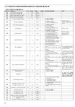
9.17
TABLES
OF
CONFIGURATIONS
ALLOWED
TO
USER
AND
INSTALLER
9.17.1
Table
of
configurations
Parameter
Description
Unit
Default
Range
Visibility
Admitted
configuration
Note
Coo
First
setpoint
in
cooling
mode
°C
7,0
5,0÷Co2
U
Hea
First
setpoint
in
heating
mode
°C
45,0
He2÷55,0
U
San
Sanitary
water
temperature
Setpoint
°C
48,0
25,0÷55,0
U
Co2
Second
setpoint
in
cooling
mode
°C
18,0
Coo÷23,0
U
He2
Second
setpoint
in
heating
mode
°C
35,0
25,0÷Hea
U
H10
Enabling
the
sanitary
function
/
0
0÷1
I
0
=
function
disabled
1
=
function
enabled
H20
ST9
input
configuration
/
0
0÷40
I
0
=
input
not
assigned
6
=
sanitary
water
temperature
SAN
‐
SAN
terminals
Input
to
be
used
in
exclusion
of
D.I.8
H21
ST10
input
configuration
/
0
0÷40
I
0
=
input
not
assigned
40
=
0
‐
10V
input
H44
DI7
configuration
/
26
0÷40
I
0
=
input
not
assigned
26
=
second
set
‐
point
humidistat
28
=
actuation
of
sanitary
thermoregulation
by
digital
input
SE
‐
SE
terminals
H45
DI8
configuration
/
0
0÷40
I
0
=
input
not
not
assigned
26
=
second
set
‐
point
humidistat
28
=
actuation
of
sanitary
thermoregulation
by
digital
input
SAN
‐
SAN
terminals
Input
to
be
used
in
exclusion
of
ST9
H54
Digital
input
polarity
/
0
0÷255
I
0
=
digital
inputs
polarity
=
NO
64
=
polarity
DI7=NC
(for
activation
of
sanitary
thermoregulator
by
digital
input,
SE
‐
SE
terminals)
128
=
polarity
DI8=NC
(for
activation
of
sanitary
thermoregulator
by
digital
input,
SAN
‐
SAN
terminals)
H58
DO3
configuration
/
22
0÷32
I
0
=
input
not
assigned
22
=
auxiliary
electric
heater
of
the
system
26
=
sanitary
water
auxiliary
electric
heater
29
=
boiler
Connect
AEH
‐
AEH
terminals
to
the
coil
of
the
contactor
(contact
NO
230Vac)
H61
Open
collector
1
configuration
/
6
0÷32
I
0
=
input
not
assigned
6
=
sanitary
water
3
‐
way
valve
22
=
auxiliary
electric
heater
of
the
system
24
=
alarm
26
=
Sanitary
water
auxiliary
electric
heater
29
=
boiler
For
the
correct
connection
to
NC1,
N1,
NO1
terminals
see
paragraphs
22.8.1
and
22.8.2.
It
is
necessary
to
use
an
external
relay
in
order
to
reduce
the
total
power
consumption
of
the
unit.
H62
Open
collector
2
configuration
/
25
0÷32
I
0
=
input
not
assigned
22
=
auxiliary
electric
heater
of
the
system
24
=
alarm
25
=
3
‐
way
vale
for
radiant
panels
26
=
Sanitary
water
auxiliary
electric
heater
29
=
boiler
For
the
correct
connection
to
NC1,
N1,
NO1
terminals
see
paragraphs
22.8.1
and
22.8.2.
It
is
necessary
to
use
an
external
relay
in
order
to
reduce
the
total
power
consumption
of
the
unit.
H76
Remote
operating
mode
selection
(summer/winter)
/
0
0÷1
I
0
=
function
disabled
1
=
function
enabled
H79
Serial
address
/
1
1÷200
I
In
case
of
several
minichillers
in
cascade
you
have
to
assign
different
addresses
to
each
control.
H82
Enabling
double
setpoint
/
0
0÷4
I
0
=
selection
menu
appears
on
CRH
1
=
classic
mode
2
=
double
cooling
setpoint
3
=
double
heating
setpoint
4
=
double
cooling
and
heating
setpoint
H83
Enabling
heating
always
diverted
towards
the
sanitary
mode
/
0
0÷1
I
0
=
disabled
function
1
=
In
heating
always
diverts
towards
the
sanitary
b04
Commutation
time
valve
radiant
panels
sec
30
0÷600
I
b08
Enabling
dynamic
set
/
0
0÷1
I
0
=
function
disabled
1
=
function
enabled
b09
Cooling
maximum
offset
°C
3.0
‐
50.0÷80.0
I
b10
Heating
maximum
offset
°C
‐
3.0
‐
50.0÷80.0
I
b11
Outdoor
air
setpoint
in
cooling
operation
°C
25
‐
127÷127
I
b12
Outdoor
air
setpoint
in
heating
operation
°C
15
‐
127÷127
I
b13
Temperature
differential
in
cooling
°C
‐
10.0
‐
50.0÷80.0
I
Summary of Contents for HPE Series
Page 21: ......
Page 29: ...28 ...
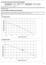
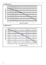
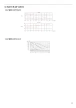
Page 31: ...30 16 WATER PUMP CURVES 16 1 MODELS HPE 06 09 16 2 MODELS HPE 12 15 ...
Page 34: ...33 19 3 HPE 12 15 IN OUT 1 M ...
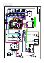
Page 35: ...34 20 WIRING DIAGRAMS 20 1 MODELS HPE 06 09 ...
Page 36: ...35 20 2 MODEL HPE 12 ...
Page 37: ...36 20 3 MODEL HPE 15 ...
Page 43: ...NOTE ...
Page 44: ...NOTE ...
Page 45: ...NOTE ...
Page 46: ...NOTE ...
Page 47: ......

