background image

RPE X - HPE X 195÷1031

3

INDICE

Pag.

Descrizione generale

5

Versioni

5

Caratteristiche costruttive

5

Accessori montati in fabbrica

5

Accessori forniti separatamente

8

Condizioni di riferimento

8

Limiti di funzionamento

8

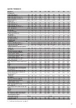
Dati tecnici

11-13

Rese in raffreddamento

19-20

Rese in riscaldamento

21-22

Perdite di carico circuito idraulico

23

Limiti portata acqua evaporatori

23

Fattori di correzione

23

Coefficienti correttivi per fattori

di sporcamento evaporatore

23

Schema circuito frigorifero:

Unità per solo raffreddamento

26

Unità a pompa di calore

27

Circuito idraulico:

Caratteristiche generali

28

Schema circuito idraulico

28

Unità con serbatoio e pompe:

Dati tecnici

31

Curve caratteristiche delle pompe

33

Dimensioni d'ingombro e spazi di rispetto

34

Posizione attacchi idraulici

35

Distribuzione pesi:

Unità per solo raffreddamento

36

Unità a pompa di calore

37

Pressione sonora

38

Sistema di regolazione con microprocessore

40

Legenda schemi circuiti elettrici

43

Schemi circuiti elettrici

46-49

Consigli pratici di installazione

50

INDEX

Pag.

General description

5

Versions

5

Technical features

5

Factory fitted accessories

5

Loose accessories

8

Reference conditions

8

Operating range

8

Technical data

11-13

Cooling capacity

19-20

Heating capacity

21-22

Water circuit pressure drops

23

Evaporator water flow limits

23

Correction factors

23

Evaporator fouling factors

corrections

23

Refrigeration circuit diagram:

Only cooling units

26

Heat pump units

27

Water circuit:
General characteristics

28

Water circuit diagram

28

Units with storage tank and pump:

Technical data

31

Characteristic pump curves

33

Dimensions and clearances

34

Position of water connections

35

Weights:

Only cooling units

36

Heat pump units

37

Sound pressure level

38

Microprocessor control system

40

Wiring diagrams explanation

43

Wiring diagrams

46-49

Installation recommendations

50

INHALTSVERZEICHNIS

Seite

Allgemeine Eigenschften

6

Bauvarianten

6

Konstruktionsmerkmale

6

Im Werk montiertes Zubehör

6

Lose mitgelieferten Zubehöre

9

Richtwerte Bedingungen am Gerätestandort

9

Einsatzbereich

9

Technische Daten

14-16

Kälteleistungen

19-20

Heizleistungen

21-22

Wärmetauscher-Druckverluste des

hydraulischen Kreislaufs

24

Verdampfer Wassermengerenzen

24

Korrektionfaktoren

24

Korrekturkoeffizienten für

Verschmutzungsfaktoren

24

Kältekreislaufschema:

Einheiten nür Kühlung

26

Einheiten nür Wärmepumpe

27

Wasserkreislauf:

Allgemeine Merkmale

29

Hydraulisches Schema

29

Einheit mit Behälter und Pumpen:

Technische Daten

31

Pumpenkennlinien

33

Außenmaße und Raumbedarf

34

Anordnung der Wasseranschlüsse

35

Gewichtsverteilung:

Einheiten nür Kühlung

36

Einheiten nür Wärmepumpe

37

Schalldruckpegel

39

Mikroprozessorregelungen

41

Schaltpläne Erklärung

44

Schaltpläne

46-49

Hinweise zur Installation

51

INDEX

Pag.

Description générale

6

Différentes versions

6

Caractéristiques techniques

6

Accessoires montés en usine

6

Accessoires fournis separement

9

Conditions de référence

9

Limites de fonctionnement

9

Données techniques

14-16

Puissance frigorifique

19-20

Puissance calorifique

21-22

Pertes de charge circuit hydraulique

24

Limites débit d'eau evaporateur

24

Facteurs de correction

24

Coefficients correcteurs pour facteurs

d’encrassements évaporateur

24

Schema du circuit frigorifique:

Groupe de production d’eau glacée 

26

Unité à pompe à chaleur

27

Circuit hydraulique:

Caractéristiques générales

29

Circuit hydraulique

29

Unité avec ballon et pompes:

Données techniques

31

Courbes caractéristiques

33

Encombrements et espaces entretien

34

Position des raccords hydrauliques

35

Distribution des poids:

Unité seul refroidissement

36

Unité à pompe à chaleur

37

Pression sonore

39

Systeme de réglage avec microprocesseur

41

Explication de le diagrammes

44

Diagrammes électriques

46-49

Conseils pratiques pour l'installation

51

Summary of Contents for RPE Series

Page 1: ...Refrigetarori d acqua e pompe di calore aria acqua con ventilatori assiali RPE X HPE X 195 1031 INFORMAZIONI TECNICHE RPE X HPE X 195 1031...

Page 2: ......

Page 3: ...planation 43 Wiring diagrams 46 49 Installation recommendations 50 INHALTSVERZEICHNIS Seite Allgemeine Eigenschften 6 Bauvarianten 6 Konstruktionsmerkmale 6 Im Werk montiertes Zubeh r 6 Lose mitgelief...

Page 4: ...ivos para factores de ensuciamiento evaporador 25 Esquema circuito frigor fico Unidades para refrigeraci n s lo 26 Unidades con bomba de calor 27 Circuito hidr ulico Caracteristicas generales 30 Esque...

Page 5: ...rifere da 196 a 1035 kW VERSIONI RPE solo raffreddamento RPE SSL solo raffreddamento super silenziata HPE pompa di calore reversibile HPE SSL pompa di calore reversibile super silenziata CARATTERISTIC...

Page 6: ...urs axiaux pour installation l ext rieur La gamme est compos e de 17 mod les d une puissance de 196 iusqu 1035 kW DIFF RENTES VERSIONS RPE uniquement refroidissement RPE SSL uniquement refroidissement...

Page 7: ...eleccionada y aquella reale y en caso de bloque parcial o total de la unidad de subrayar quales seguridades intervenieron Circuitos frigorificos versiones RPE RPE SSL Cada unidad incluye dos circuitos...

Page 8: ...e accessory is rquired This value can be reduced until 20 C with an optional accessory supplied prefabricated 1 In all cases the water range will have to re enter within the reported limits on pag 23...

Page 9: ...r zur cklegen niedrige Temperatur Es kann auf 20 C mit dem Zusatzger t reduziert werden Kondensation Kontrolle 1 Die Wasser Durchflu menge muss jedenfalls den auf der Tabelle Seite 24 Grenzen entsprec...

Page 10: ...lefacci n temperatura entrada agua 40 C temperatura salida agua 45 C aire en la entrada bater a 7 C b s 6 C b u presi n sonora DIN 45635 medida en campe libre a 1 m de distancia y a 1 5 m del suelo se...

Page 11: ...ressione sonora ISO 1 dB A 66 5 66 5 67 5 69 5 67 5 69 5 Sound pressure level ISO 1 Pressione sonora con accessorio SL ISO 1 dB A 63 5 63 5 64 5 66 5 64 5 65 5 Sound pressure level with SL accessory I...

Page 12: ...onora ISO 1 dB A 70 5 68 5 69 5 68 5 70 5 dB A Sound pressure level ISO 1 Pressione sonora con accessorio SL ISO 1 dB A 66 5 65 5 66 5 65 5 67 5 dB A Sound pressure level with SL accessory ISO 1 Caric...

Page 13: ...5 83 5 84 5 Sound pressure level with SL accessory DIN 1 Pressione sonora ISO 1 dB A 72 5 73 5 73 5 73 5 73 5 74 5 Sound pressure level ISO 1 Pressione sonora con accessorio SL ISO 1 dB A 69 5 70 5 7...

Page 14: ...IN 1 Schalldruckpegel ISO 1 dB A 66 5 66 5 67 5 69 5 67 5 69 5 Pression sonore ISO 1 Schalldruckpegel mit Zubeh r SL ISO 1 dB A 63 5 63 5 64 5 66 5 64 5 65 5 Pression sonore avec accessoire SL ISO 1 K...

Page 15: ...uckpegel ISO 1 dB A 70 5 68 5 69 5 68 5 70 5 Pression sonore ISO 1 Schalldruckpegel mit Zubeh r SL ISO 1 dB A 66 5 65 5 66 5 65 5 67 5 Pression sonore avec accessoire SL ISO 1 K ltemittelf llung R410A...

Page 16: ...1 dB A 81 5 82 5 82 5 83 5 83 5 84 5 Pression sonore avec accessoire SL DIN 1 Schalldruckpegel ISO 1 dB A 72 5 73 5 73 5 73 5 73 5 74 5 Pression sonore ISO 1 Schalldruckpegel mit Zubeh r SL ISO 1 dB A...

Page 17: ...5 75 5 76 5 78 5 76 5 78 5 Presi n sonora ISO 1 dB A 66 5 66 5 67 5 69 5 67 5 69 5 70 5 68 5 69 5 Presi n sonora con accesorio SL ISO 1 dB A 63 5 63 5 64 5 66 5 64 5 65 5 66 5 65 5 66 5 Carga refriger...

Page 18: ...accesorio SL DIN 1 dB A 77 5 79 5 81 5 82 5 82 5 83 5 83 5 84 5 Presi n sonora ISO 1 dB A 68 5 70 5 72 5 73 5 73 5 73 5 73 5 74 5 Presi n sonora con accesorio SL ISO 1 dB A 65 5 67 5 69 5 70 5 70 5 70...

Page 19: ...126 220 106 7 374 93 0 362 98 0 346 106 334 113 313 126 229 106 8 388 93 0 376 98 0 360 106 347 113 325 126 238 106 9 403 92 0 391 98 0 374 106 361 113 338 125 248 106 10 419 92 0 406 98 0 388 106 37...

Page 20: ...289 782 306 722 338 573 315 6 921 254 891 268 847 289 812 306 749 338 596 315 7 955 254 924 268 879 289 843 306 778 338 619 315 8 990 254 958 268 912 289 875 306 807 338 643 315 9 1025 254 993 268 945...

Page 21: ...345 122 7 87 383 100 374 110 365 122 10 70 395 100 384 110 373 122 15 60 457 99 442 110 428 122 361 0 90 323 109 318 120 314 133 5 90 394 109 385 120 378 133 7 87 417 109 408 120 399 133 10 70 432 108...

Page 22: ...We 590 0 90 577 183 566 203 557 225 5 90 669 183 653 203 638 225 7 87 709 183 691 203 674 225 10 70 774 182 752 202 731 225 15 60 891 181 863 201 834 224 667 0 90 665 202 652 225 639 250 5 90 772 202...

Page 23: ...SSURE DROPS LIMITI PORTATA ACQUA EVAPORATORI EVAPORATORS WATER FLOW LIMITS Modello 195 221 246 270 298 331 361 395 435 485 543 590 667 749 833 924 1031 Model Portata minima l s 5 8 6 5 6 8 7 7 8 6 10...

Page 24: ...DRUCKVERLUSTEDES HYDRAULISCHEN KREISLAUFS PERTES DE CHARGE CIRCUIT HYDRAULIQUE Glykol Prozent pro Gewicht 0 10 20 30 40 50 Pourcentage de glycole ethyl nique en poids Gefriertemperatur C 0 4 5 9 5 15...

Page 25: ...55 0 942 1 1 082 1 154 Multiplicador de potencia en Free Cooling 1 095 1 071 1 045 1 0 943 0 874 COEFFICIENTES CORRECTIVOS PARA FACTORES DE ENSUCIAMIENTO EVAPORADOR f1 fp1 0 Placas limpias 1 1 0 44 x...

Page 26: ...ore di liquido Sight glass Schauglas Indicateur de liquide Indicador de l quido SPH Pressostato di alta pressione High pressure switch Hochdruckw chter Pressostat de haute pression Presostato de alta...

Page 27: ...Water cooled exchanger Wassergek hlter W rmetauscher changeur eau Intercambiador de agua SF Indicatore di liquido Sight glass Schauglas Indicateur de liquide Indicador de l quido SLG Separatore liquid...

Page 28: ...t PS Water circuit with additional circulation pump Includes evaporator temperature sensor antifreeze sensor differential water pressure switch circulation pump expansion vessel safety valve and therm...

Page 29: ...differentialem Wasserdruckschlater und Wasser Entladen PS Wasserkreislauf mit zus tzlicher Umlaufpumpe Bestehend aus Verdampfer Temperaturf hler Frostschutzf hler dif ferentialem Wasserdruckschlater U...

Page 30: ...D Circuitohidr ulicoconaccesoriodoble bomba decirculaci n Incluye evaporador sondadetrabajo sondaantihielo presostatodiferencial agua doble bombadecirculaci n vased expansi n v lvuladeseguridad y rele...

Page 31: ...to ed attacchi idraulici Zuz glich Betriebsgewicht und Wasseranschl sse der Ger te Additional weight in operation and water connections Poids suppl mentaire en fonctionnement et raccords hydrauliques...

Page 32: ...uina de referencia De esta manera es posible calcular el peso total de la unidad en funci n importante para la definici n de la base de suporte y para los eventuales antivibrantes Peso adicional en ma...

Page 33: ...delle pompe EINHEIT MIT BEH LTER UND PUMPEN Pumpenkennlinien UNITS WITH PUMPS Characteristic pump curves UNITES AVEC POMPES Courbes caract ristiques UNIDADES CON BOMBAS Curvas caracteristicas Mod RPE...

Page 34: ...00 2200 2200 2200 2200 2200 2200 2200 2200 2200 2200 2200 2200 2200 C mm 2100 2100 2100 2100 2100 2100 2100 2100 2100 2100 2100 2100 2100 2100 2100 2100 2100 2100 2100 2100 2100 2100 2100 2100 2100 21...

Page 35: ...30 330 330 330 330 330 E mm 960 960 960 960 960 960 960 960 960 960 960 960 960 960 960 960 960 D1 mm 960 960 960 960 960 960 960 960 960 960 960 960 960 960 960 960 960 E1 mm 1500 1500 1500 1500 1500...

Page 36: ...345 K8 kg 270 275 285 300 305 315 315 320 330 320 325 330 320 325 340 K9 kg 310 315 330 K10 kg 300 305 320 K11 kg K12 kg K13 kg K14 kg Tot kg 1670 1700 1780 1690 1720 1810 1780 1810 1900 1980 2010 209...

Page 37: ...SSL STD SL SSL K1 kg 385 395 400 400 410 420 410 420 430 430 440 400 420 430 415 445 455 430 435 445 445 455 K2 kg 375 380 385 390 395 410 395 400 415 420 425 385 415 420 400 440 445 415 425 430 435 4...

Page 38: ...80 1 81 2 79 4 80 9 80 3 82 1 83 8 84 9 85 0 85 7 86 0 86 9 SL MODELLO MODEL 195 221 246 270 298 331 361 395 435 485 543 590 667 749 833 924 1031 Hz dB A dB A dB A dB A dB A dB A dB A dB A dB A dB A...

Page 39: ...B A 63 62 0 62 1 62 8 64 0 63 3 63 5 64 9 63 3 64 8 64 0 65 3 67 3 68 2 68 4 68 9 69 3 69 9 125 65 1 65 4 66 3 68 1 66 3 67 4 69 0 67 3 69 0 68 3 69 7 71 9 72 9 73 2 73 9 74 4 75 1 250 65 6 65 8 67 2...

Page 40: ...ri antigelo pressostato differenziale errore configurazione Accessori Interfaccia seriale per PC remotazione display MICROPROCESSOR CONTROL SYSTEM A microprocessor controls all the functions of the un...

Page 41: ...mpresseur antigel pressostatdiff rentiel erreur Eeprom Accessoires Interface s rielle pour PC Installation distance du viseur MIKROPROZESSORREGELUNGEN DiegesamteRegelungundKontrollederAnlageerfolgt mi...

Page 42: ...ci n Funciones principales Indicaci n temperatura de entrada y de salida agua identificaci n y visaulizaci n de los bloques por medio de un c digo alfan merico regolaci n de una o dos bombas retardo e...

Page 43: ...RCUIT RC RES CARTER COMPRESSORE COMP CRANKCASE HEATER REV RESISTENZA EVAPORATORE EVAPORATOR HEATER RF REL DI FASE PHASE SEQUENCE RELAY RG REGOLATORE DI GIRI SPEED GOVERNOR RQ RES QUADRO ELETTRICO ELEC...

Page 44: ...MPRESSEUR REV VERDAMPFER ELEKTROHEIZUNG RESISTANCE EVAPORATEUR RF PHASENRELAIS RELAIS SEQUENCE PHASE RG DREHZALREGLER REGULATEUR VITESSE RQ SCHALTSCHRANK ELEKTROHEIZUNG RESISTANCE CADRE ELECTRIQUE RTC...

Page 45: ...UITO RC RESISTENCIA C RTER COMPRESOR REV RESISTENCIA DEL EVAPORADOR RF RELE DE FASE RG REGULADOR DE VELOCIDAD RQ RESISTENCIA CUADRO EL CTRICO RTC RELE TERMICO COMPRESOR RTP RELE TERMICO BOMBA SA SONDA...

Page 46: ...ar durante la instalaci n RG1 MV 1 L1 400V 50Hz 3Ph P E PE L3 L2 SG KV1 X1 RT V7 RT V2 RT V1 L2 L1 PE L3 L2 L1 L3 PE MV 2 L3 L2 L1 PE MV 3 L1 L2 MV4 RT V3 MV6 L1 L3 PE RT V4 MV5 L2 L3 PE RT V5 RT V6 L...

Page 47: ...O9 C12 C13 15 NO11 NO12 NO15 NO13 NO14 NO16 C16 18 NO17 NO18 C19 20 NO19 AI1 AIC1 NO20 AI3 AI2 AIC2 AIC4 AI4 AIC3 12VDC AI5 AIC5 12VDC AI6 AIC7 AIC6 6 5 4 1 2 3 1 4 3 2 RTC1 RTC2 RTC3 RTC4 RTC5 RTC6 R...

Page 48: ...neas punteadas indican las conexiones opcionales o que se deben realizar durante la instalaci n FC4 KC4 MC 5 KC1 400V 50Hz 3Ph P E SG PE L1 L2 L3 PE L3 PE PE L2 L3 MC 1 L1 L1 L2 MC 2 PE MC 3 L1 PE PE...

Page 49: ...4 L2 L3 IDL1 KC8 KC5 KC4 KC7 KC6 KC10 KC9 KC12 KC11 IDLC1 2 IDLC3 IDLC3 4 IDL2 IDL5 IDLC5 6 IDLC4 IDL7 IDLC7 8 IDL6 IDLC9 IDLC9 10 IDL8 IDLC15 18 IDL11 IDLC11 14 IDL10 IDL13 IDL12 IDL15 IDL14 IDL17 ID...

Page 50: ...ttazione valvola di taratura giunti antivibranti ecc Avviamento e manutenzione Attenersi scrupolosamente a quanto indicato nel manuale di uso e manutenzione Tali operazioni devono comunque essere effe...

Page 51: ...rage jonctions antivibratiles etc Mise en service et entretien Se tenir scrupuleusement ce qui est indiqu dans le manuel d utilisation et d entretien Ces op rations seront toutefois effectu es par du...

Page 52: ...por medio del mando remoto Antes de entrar en el interior desconectar la alimentaci n abriendo el seccionador general Serecomiendaencarecidamentelainstalaci ndeuninterruptor magnet rmico para la prote...

Page 53: ...53 NOTE...

Page 54: ...54...

Page 55: ......

Page 56: ...A2B Accorroni E G s r l Via d Ancona 37 60027 Osimo An Tel 071 723991 r a Fax 071 7133153 web site www accorroni it e mail a2b accorroni it...

Reviews: