5
/
20
IMMEDIATELY.
1.
Lifting
WARNING:
NEVER ATTEMPT TO LIFT THIS MACHINE USING THE SPINDLE OR ANY HANDWHEEL.
a). There is a M12 Eye Bolt in the top of the spindle housing. Be sure the eye bolt is down tight.
b). Using the eye bolt as a lifting point, place the machine in its predetermined location and
secure using the three mounting lugs on the machine base.
2. Thoroughly clean the machine, using a soft cloth and an approved solvent, to remove any
preservative coating.
WARNING:
DO NOT use lacquer thinner.
3. Be sure all switches are in the OFF position.
CAUTION:
DO NOT attempt to test or operate this machine until you are completely familiar with
the functions of all of the controls and switches.
DISC TRUING ATTACHMENT
The disc truing attachment can be mounted in any one of three positions
(See Figure 4), depending on the diameter of the disc. The maximum travel
of the slide in any position is 4”.
1). Select the appropriate threaded hole in the feed slide plate and screw
one end of the clamp stud into it.
2). Place one of the slotted holes of the disc attachment over the stud.
Add the spacer and the washer. (Figure 5) Secure the attachment using
the clamp handle.
Note:
Final location of the disc attachment can be made after the disc
rotor to be machined has been installed.
DRUM TRUING ATTACHMENT
The drum truing attachment can be mounted in any one of three locations
depending on the diameter of the drum.
1). Select the appropriate threaded hole in the feed slide plate and screw
one end of the clamp stud into it.
2). Place the tool bar tube over the clamp stud, add the washer and secure
using the clamp handle. (Figure 6)
NOTE:
Final location of the drum attachment can be made after the
drum has been installed.
ARBOR ATTACHMENT
The standard arbor, mounts quickly to the spindle receptacle using a
threaded draw bar and hand wheel. (Figure 7)
1. Insert the arbor, threaded hole first, into the spindle receptacle at
the left end of the spindle housing, carefully make mark.
NOTE:
Make certain mating surfaces on the arbor and spindle are clean and free of nicks and
gouges. The smallest nick or scratch can cause incorrect drum or rotor alignment resulting in
inaccurate resurfacing.
WARNING:
Never loosen or attempt to remove arbor with a disc or drum mounted.
2. Turn the draw bar hand wheel until the arbor is drawn up tight.
NOTE:
To remove the arbor, give the draw bar hand wheel a quick counter-clockwise turn to
loosen. Continued counter-clockwise rotation frees the draw bar from the arbor allowing the
Summary of Contents for C9372
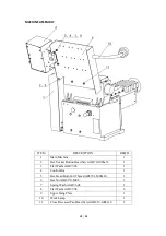
Page 13: ...13 20 Cross Feed Feed Slide Assembly ...
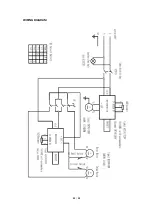
Page 20: ...20 20 WIRING DIAGRAM ...


