background image


Chapter 3 – AMI BIOS Setup 


28


In

fo

tain

m

en

t M

ult

i-T

ou

ch

 P

an

el 

PC


AC

P-

10

76


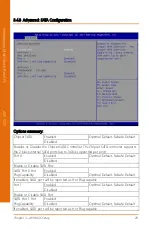
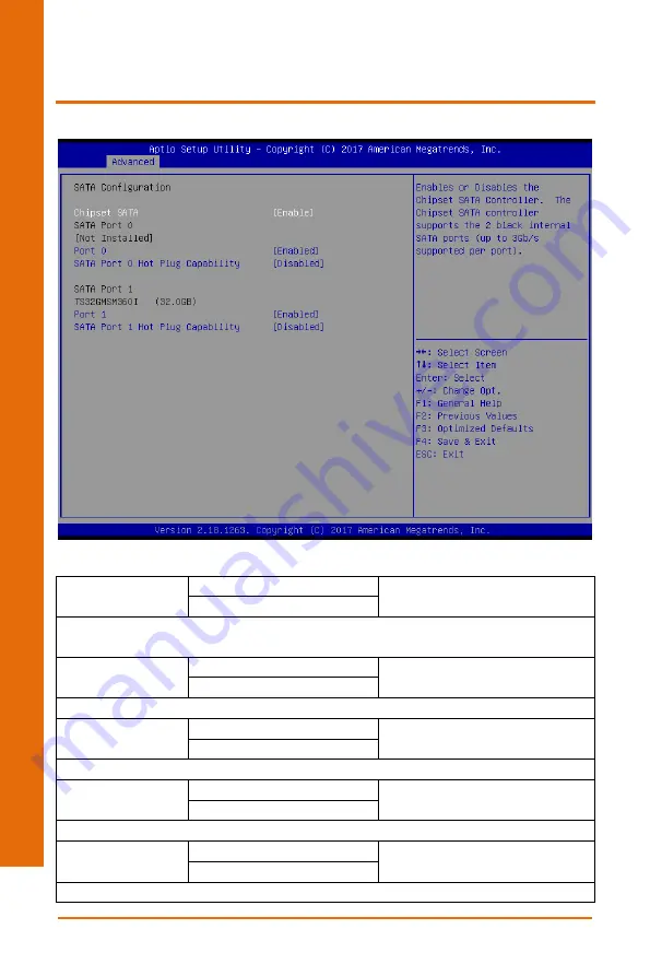
3.4.3 Advanced: SATA Configuration 


Options summary: 

Chipset SATA 
 

Enabled 

Optimal Default, Failsafe Default 

Disabled 

Enables or Disables the Chipset SATA Controller. The Chipset SATA controller supports 
the 2 black internal SATA ports (up to 3Gb/s supported per port) 
Port 0 

Enabled 

Optimal Default, Failsafe Default 

Disabled 

Enable or Disable SATA Port. 
SATA Port 0 Hot 
PlugCapability 

Enabled 

 
Optimal Default, Failsafe Default 

Disabled 

If enabled, SATA port will be reported as Hot Plug capable 
Port 1 
 

Enabled 

Optimal Default, Failsafe Default 

Disabled 

Enable or Disable SATA Port. 
SATA Port 1 Hot 
PlugCapability   

Enabled 

 
Optimal Default, Failsafe Default 

Disabled 

If enabled, SATA port will be reported as Hot Plug capable 

Summary of Contents for ACP-1076

Page 1: ...Last Updated July 27 2017 ACP 1076 7 Infotainment Multi Touch Panel PC User s Manual 1st Ed...

Page 2: ...ovided in this manual is intended to be accurate and reliable However the original manufacturer assumes no responsibility for its use or for any infringements upon the rights of third parties that may...

Page 3: ...egistered trademark of Microsoft Corp Intel Pentium Celeron and Xeon are registered trademarks of Intel Corp Core Atom are trademarks of Intel Corporation ITE is a trademark of Integrated Technology E...

Page 4: ...List Before setting up your product please make sure the following items have been shipped Item Quantity ACP 1076 1 Panel mount kit 1 Product DVD 1 If any of these items are missing or damaged please...

Page 5: ...ch as detailed descriptions and explanations on the product s hardware and software features if any its specifications dimensions jumper connector settings definitions and driver installation instruct...

Page 6: ...on the system s hardware 6 No connections should be made when the system is powered as a sudden rush of power may damage sensitive electronic components 7 If the device is not to be used for a long ti...

Page 7: ...ntainers 18 If any of the following situations arises please the contact our service personnel i Damaged power cord or plug ii Liquid intrusion to the device iii Exposure to moisture iv Device is not...

Page 8: ...of explosion if the battery is incorrectly replaced Replace only with the same or equivalent type recommended by the manufacturer Dispose of used batteries according to the manufacturer s instruction...

Page 9: ...Preface IX Infotainment Multi Touch Panel PC ACP 1076 China RoHS Requirements CN AAEON Panel PC Workstation Pb Hg Cd Cr VI PBB PBDE O SJ T 11363 2006 X SJ T 11363 2006...

Page 10: ...rnal Connections O O O O O O Chassis O O O O O O CPU RAM O O O O O O Hard Disk O O O O O O LCD O O O O O O Optical Drive O O O O O O Touchscreen O O O O O O PSU O O O O O O O The quantity of poisonous...

Page 11: ...rol Mode Selection JP2 10 2 3 4 COM2 Pin8 Function Selection JP3 10 2 3 5 COM3 Pin8 Function Selection JP4 11 2 3 6 Auto Power Button Enable Disable Selection JP5 11 2 3 7 Front Panel Connector JP6 11...

Page 12: ...ion 29 3 4 5 Advanced Hardware Monitor 31 3 4 6 Advanced SIO Configuration 32 3 4 7 Advanced Power Management 36 3 5 Setup submenu Chipset 37 3 5 1 North Bridge 38 3 6 Setup submenu Security 40 3 7 Se...

Page 13: ...Infotainment Multi Touch Panel PC ACP 1076 Chapter 1 Chapter 1 Product Specifications...

Page 14: ...ntroller LVDS I O Port USB 3 0 x 2 USB 2 0 x 1 LAN x 2 DB9 x 2 for RS232 RS422 RS485 DB9 x 1 for RS232 HDMI x 1 Antenna Hole x 2 Power Button x 1 Lockable Power Connector x 1 AAEON Expansion slot x 1...

Page 15: ...lb Gross Weight 2 1 kg 4 63 lb Environmental Operating Temperature 5 50 C 23 122 F with airflow Storage Temperature 20 70 C 4 158 F Operating Humidity 10 90 40oC non condensing Anti Vibration 3 Grms 5...

Page 16: ...Chapter 1 Product Specifications 4 Infotainment Multi Touch Panel PC ACP 1076 Contrast Ratio 600 1 Viewing Angle 120 H 120 V Touchscreen Type USB Resolution 2048 x 2048 Light Transmission 90...

Page 17: ...Infotainment Multi Touch Panel PC ACP 1076 Chapter 2 Chapter 2 Hardware Information...

Page 18: ...Chapter 2 Hardware Information 6 Infotainment Multi Touch Panel PC ACP 1076 2 1 Dimensions...

Page 19: ...Chapter 2 Hardware Information 7 Infotainment Multi Touch Panel PC ACP 1076 2 2 Jumpers and Connectors Jumpers Board Component Side...

Page 20: ...Chapter 2 Hardware Information 8 Infotainment Multi Touch Panel PC ACP 1076 Connectors COM Option USB Option...

Page 21: ...ure for your application Label Function JP1 LVDS Port1 Backlight Inverter VCC Selection and Operating VDD Selection JP2 LVDS Port1 Backlight Lightness Control Mode Selection JP3 COM2 Pin8 Function Sel...

Page 22: ...Pin8 Function Selection JP3 12V Ring Default 5V 1 2 3 4 5 6 1 2 3 4 5 6 1 2 3 4 5 6 1 2 3 4 5 6 1 2 3 1 2 3 1 2 3 4 5 6 1 2 3 4 5 6 1 2 3 4 5 6 1 2 3 4 5 6 1 2 3 4 5 6 1 2 3 4 5 6 1 2 3 4 5 6 1 2 3 4...

Page 23: ...in Name Pin Pin Name 1 PWR_BTN 2 PWR_BTN 3 HDD_LED 4 HDD_LED 5 SPEAKER 6 SPEAKER 7 PWR_LED 8 PWR_LED 9 H W RESET 10 H W RESET 5 6 5 6 1 2 3 4 5 6 1 2 3 4 5 6 5 6 5 6 1 2 3 4 5 6 1 2 3 4 5 6 5 6 1 2 3...

Page 24: ...Information 12 Infotainment Multi Touch Panel PC ACP 1076 2 3 8 Touch Screen 4 5 8 Wire Selection JP9 4 8 Wires Mode 5 Wires Mode Default 2 3 9 Clear CMOS Jumper JP10 Normal Default Clear CMOS 1 2 3...

Page 25: ...Connectors Please refer to the table below for all of the board s connectors that you can configure for your application Label Function Power Power on off USB 2 0 USB 2 0 COM2 COM3 RS232 RS422 RS485 D...

Page 26: ...uch Panel PC ACP 1076 2 4 1 Power Button ON OFF 2 4 2 USB 2 0 port Pin Pin Name Pin Pin Name 1 5VSB PWR 5V 2 USB4_D DIFF 3 USB4_D DIFF 4 GND GND 2 4 3 USB 2 0 port x 2 optional Pin Pin Name Pin Pin Na...

Page 27: ...3 Port RS232 RS422 RS485 RS 232 Pin Pin Name Pin Pin Name 1 DCD IN 2 RX IN 3 TX OUT 5V 4 DTR OUT 5V 5 GND GND 6 DSR IN 7 RTS OUT 5V 8 CTS IN 9 RI 5V 12V IN PWR 5V 12V RS 422 Pin Pin Name Pin Pin Name...

Page 28: ...Panel PC ACP 1076 8 NC 9 NC 5V 12V PWR 5V 12V RS 485 Pin Pin Name Pin Pin Name 1 RS485_D I O 5V 2 RS485_D I O 5V 3 NC 4 NC 5 GND GND 6 NC 7 NC 8 NC 9 NC 5V 12V PWR 5V 12V 2 4 5 DC In connector 2 4 6...

Page 29: ...9V 5 GND GND 6 DSR IN 7 RTS OUT 9V 8 CTS IN 9 RI IN 2 4 7 HDMI port Pin Pin Name Signal Type Signal level 1 TMDS_DAT2 DIFF 2 GND GND 3 TMDS_DAT2 DIFF 4 TMDS_DAT1 DIFF 5 GND GND 6 TMDS_DAT1 DIFF 7 TMD...

Page 30: ...G_DETECT IN 2 4 8 USB 3 0 port x 2 Pin Pin Name Signal Type Signal Level 1 5VSB PWR 5V 2 USB_D DIFF 3 USB_D DIFF 4 GND GND 5 USB_SSRX DIFF 6 USB_SSRX DIFF 7 GND GND 8 USB_SSTX DIFF 9 USB_SSTX DIFF 10...

Page 31: ...i Touch Panel PC ACP 1076 16 GND GND 17 USB_SSTX DIFF 18 USB_SSTX DIFF 2 4 9 LAN port x 2 Pin Pin Name Signal Type Signal level 1 MDI0 DIFF 2 MDI0 DIFF 3 MDI1 DIFF 4 MDI2 DIFF 5 MDI2 DIFF 6 MDI1 DIFF...

Page 32: ...Infotainment Multi Touch Panel PC ACP 1076 Chapter 3 Chapter 3 AMI BIOS Setup...

Page 33: ...tines check the current system configuration against the values stored in the CMOS memory If they do not match an error message will be outputted in which case you will need to run the BIOS setup prog...

Page 34: ...etained when the power is turned off To enter BIOS Setup press Del immediately while your computer is powering up The function for each interface can be found below Main Date and time can be set here...

Page 35: ...Chapter 3 AMI BIOS Setup 23 Infotainment Multi Touch Panel PC ACP 1076 3 3 Setup Submenu Main...

Page 36: ...Chapter 3 AMI BIOS Setup 24 Infotainment Multi Touch Panel PC ACP 1076 3 4 Setup Submenu Advanced...

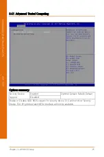
Page 37: ...3 4 1 Advanced Trusted Computing Options summary Security Device Support Enabled Optimal Default Failsafe Default Disabled Enable or Disable SATA BIOS support for security device O S will not show Sec...

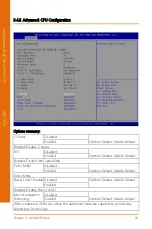
Page 38: ...l Default Failsafe Default Enabled Enabled Disable Intel SpeedStep Turbo Mode Disabled Optimal Default Failsafe Default Enabled Turbo Mode Power Limit 1 Enable Disabled Optimal Default Failsafe Defaul...

Page 39: ...Chapter 3 AMI BIOS Setup 27 Infotainment Multi Touch Panel PC ACP 1076 VT d Disabled Optimal Default Failsafe Default Enabled Enabled Disable CPU VT d...

Page 40: ...SATA ports up to 3Gb s supported per port Port 0 Enabled Optimal Default Failsafe Default Disabled Enable or Disable SATA Port SATA Port 0 Hot PlugCapability Enabled Optimal Default Failsafe Default D...

Page 41: ...Chapter 3 AMI BIOS Setup 29 Infotainment Multi Touch Panel PC ACP 1076 3 4 4 Advanced PCI Express Configuration...

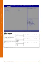
Page 42: ...tions summary PCIE Slot CN33 Enable Optimal Default Failsafe Default Disable Control PCIE Slot CN33 Hot Plug Disable Optimal Default Failsafe Default Enable PCI Express Hot Plug Enable Disable PCIe Sp...

Page 43: ...Chapter 3 AMI BIOS Setup 31 Infotainment Multi Touch Panel PC ACP 1076 3 4 5 Advanced Hardware Monitor...

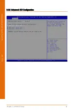
Page 44: ...Chapter 3 AMI BIOS Setup 32 Infotainment Multi Touch Panel PC ACP 1076 3 4 6 Advanced SIO Configuration...

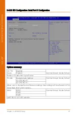
Page 45: ...ions summary Use This Device Disabled Enabled Optimal Default Failsafe Default Enable or Disable this Logical Device Possible Use Automatic Settings Optimal Default Failsafe Default IO 2F8 IRQ 3 IO 3F...

Page 46: ...ed Optimal Default Failsafe Default Enable or Disable this Logical Device Possible Use Automatic Settings Optimal Default Failsafe Default IO 2F8 IRQ 3 IO 3F8 IRQ 4 Allows user to change Device s Reso...

Page 47: ...d Optimal Default Failsafe Default Enable or Disable this Logical Device Possible Use Automatic Settings Optimal Default Failsafe Default IO 3E8 IRQ 11 IO 2E8 IRQ 11 Allows user to change Device s Res...

Page 48: ...elect power supply mode Restore AC Power Loss Last State Optimal Default Failsafe Default Always On Select power state when power is re applied after a power failure RTC wake system from S5 Disabled O...

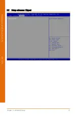
Page 49: ...Chapter 3 AMI BIOS Setup 37 Infotainment Multi Touch Panel PC ACP 1076 3 5 Setup submenu Chipset...

Page 50: ...Chapter 3 AMI BIOS Setup 38 Infotainment Multi Touch Panel PC ACP 1076 3 5 1 North Bridge...

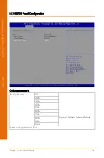
Page 51: ...IOS Setup 39 Infotainment Multi Touch Panel PC ACP 1076 3 5 1 1 LVDS Panel Configuration Options summary Backlight Level 10 Optimal Default Failsafe Default 20 30 40 50 60 70 80 90 100 Select backligh...

Page 52: ...oes not provide access to many of the features in the Setup utility Select the password you wish to set press Enter to open a dialog box to enter your password you can enter no more than six letters o...

Page 53: ...Failsafe Default Enables or disables Quiet Boot option Monitor Mwait Disabled Enabled Auto Optimal Default Failsafe Default Enable Disable Monitor Mwait To install Linux OS please set this item to dis...

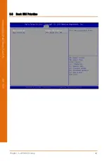
Page 54: ...Chapter 3 AMI BIOS Setup 42 Infotainment Multi Touch Panel PC ACP 1076 3 8 Boot BBS Priorities...

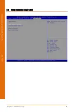
Page 55: ...Chapter 3 AMI BIOS Setup 43 Infotainment Multi Touch Panel PC ACP 1076 3 9 Setup submenu Save Exit...

Page 56: ...Infotainment Multi Touch Panel PC ACP 1076 Chapter 4 Chapter 4 Drivers Installation...

Page 57: ...P 1 CHIPSET folder and followed by SetupChipset exe file 2 Follow the instructions 3 Drivers will be installed automatically Step 2 Install Graphics Driver 1 Open the STEP 2 VGA folder and followed by...

Page 58: ...Infotainment Multi Touch Panel PC ACP 1076 Appendix A Appendix A Watchdog Timer Programming...

Page 59: ...alue Note Timer Counter 0x07 Note3 0xF6 Note4 Note24 Time of watchdog timer 0 255 This register is byte access Counting Unit 0x07 Note5 0xF5 Note6 3 Note7 0 Note8 Select time unit 0 second 1 minute Wa...

Page 60: ...This parameter is represented from Note8 define byte EnableLDN This parameter is represented from Note9 define byte EnableReg This parameter is represented from Note10 define byte EnableBit This para...

Page 61: ...t Multi Touch Panel PC ACP 1076 VOID Main Procedure AaeonWDTConfig byte Timer Time of WDT timer 0x00 0xFF boolean Unit Select time unit 0 second 1 minute AaeonWDTConfig Procedure AaeonWDTEnable This p...

Page 62: ...T relative parameter setting WDTParameterSetting VOID WDTEnableDisable byte LDN byte Register byte BitNum byte Value SIOBitSet LDN Register BitNum Value VOID WDTParameterSetting Watchdog Timer counter...

Page 63: ...DN Register Offset 0x07 IOWriteByte SIOData LDN VOID SIOBitSet byte LDN byte Register byte BitNum byte Value Byte TmpValue SIOEnterMBPnPMode SIOSelectLDN byte LDN IOWriteByte SIOIndex Register TmpValu...

Page 64: ...Infotainment Multi Touch Panel PC ACP 1076 Appendix B Appendix B I O Information...

Page 65: ...Appendix B I O Information 53 Infotainment Multi Touch Panel PC ACP 1076 B 1 I O Address Map...

Page 66: ...Appendix B I O Information 54 Infotainment Multi Touch Panel PC ACP 1076 B 2 Memory Address Map...

Page 67: ...Appendix B I O Information 55 Infotainment Multi Touch Panel PC ACP 1076 B 3 IRQ Mapping Chart...

Page 68: ...Appendix B I O Information 56 Infotainment Multi Touch Panel PC ACP 1076...

Page 69: ...Appendix B I O Information 57 Infotainment Multi Touch Panel PC ACP 1076...

Page 70: ...Appendix B I O Information 58 Infotainment Multi Touch Panel PC ACP 1076...

Page 71: ...Appendix B I O Information 59 Infotainment Multi Touch Panel PC ACP 1076...

Page 72: ...Appendix B I O Information 60 Infotainment Multi Touch Panel PC ACP 1076...

Page 73: ...Appendix B I O Information 61 Infotainment Multi Touch Panel PC ACP 1076...

Page 74: ...Appendix B I O Information 62 Infotainment Multi Touch Panel PC ACP 1076...

Page 75: ...Appendix B I O Information 63 Infotainment Multi Touch Panel PC ACP 1076...

Reviews: