background image


AMB-2020HT(T)-E User’s Manual 

15 


2.1 Jumpers on the EI5CM 


The jumpers on EI5CM allow you to configure your system to your applications. The following table lists 
the jumper functions on the board. 


Jumper Locations on the EI5CM 

15 

SW3: CPU Voltage Selector 

16 

JP10: RS232/422/485 (COM2) Selection  16 

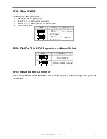
JP12: Clear CMOS   17 

JP16: DiskOnChip BIOS Expansion Address Select   17 

JP14: Reset Button Connector  17 


Remarks

: The following conventions are used in this section: 


off off on on


OPEN 


SHORT  


Jumper Locations on the EI5CM 


DISK ON CHIP


Summary of Contents for AMB-2020HT-E Series

Page 1: ...AMB 2020HT T E User s Manual 1 AMB 2020HT T E Series Open Frame Modular Industrial Panel PCs Version 1 0 Industrial Panel PCs Industrial Panel PCs for Industrial Automation User s Manual ...

Page 2: ...r product information only and is subject to change without notice While reasonable efforts have been made in the preparation of this document to assure its accuracy AAEON assumes no liabilities resulting from errors or omissions in this document or from the use of the information contained herein AAEON reserves the right to make changes in the product design without notice to its users Acknowledg...

Page 3: ...Manual Drivers and Utilities n Accessory Metal cover for LCD connector CD ROM and Floppy drive s cover Power cables for HDD FDD Screws bag 50 pin Cable 1M Power cord 1 8 M Wire cable for external power Mounting kits Waterproof sponge With the touchscreen option Touch pen If any of these items are missing or damaged you should contact your distributor or sales representative immediately ...

Page 4: ...g over the power cord 10 All cautions and warnings on the equipment should be noted 11 If the equipment is not used for a long time disconnect it from the power source to avoid damage by transient over voltage 12 Never pour any liquid into an opening This could cause fire or electrical shock 13 Never open the equipment For safety reasons only qualified service personnel should open the equipment 1...

Page 5: ...tions 8 1 3 Touchscreen Optional 10 1 4 LCD Specifications 10 1 5 Dimensions 11 1 6 Panel Mounting 12 1 7 Waterproof Sponge Position 13 Chapter 2 Jumper Settings 14 2 1 Jumpers on the EI5CM 15 Chapter 3 BIOS Configuration 18 BIOS Introduction 19 BIOS Setup 20 Standard CMOS Setup 21 BIOS Features Setup 24 Chipset Features Setup 27 Power Management Setup 29 ...

Page 6: ...AMB 2020HT T E User s Manual 6 1 Chapter1 General Information ...

Page 7: ...x 600 color TFT hi brightness long life time LCD display and compact with different control modules The compact dimensions are ideal for automation applications when the installation space is critical These PCs are characterized by their space saving there is one free slot for PCI ISA AMB 2020HT T E is heavy duty steel chassis and optional aluminum front panel which meets the toughest industrial a...

Page 8: ... on the rear panel n Disk Driver Space for CD ROM FDD and HDD n DiskOnChip flash disk socket n Resistive touchscreen optional n Rotatable Mounting mechanism optional n Aluminum front bezel optional Features of EI5CM Single Board Computer n Processor Cyrix MediaGXLV MMX ENHANCED n Chipset Cyrix Cx5530 n Memory Up to 128MB in SDRAM n VGA Support XpressGRAPHICS and integrated on the process n Audio S...

Page 9: ...y Supports up to 128MB l Display 12 1 SVGA 800 x 600 TFT color LCD l LCD CRT controller NS Cx5530 Chipset UMA supports up to 2 5MB display memory l Network LAN Realtek RTL8139B 10 100 Base T Ethernet controller l I O ports 4 serial ports 3 x RS 232 1 x RS 232 422 485 one is reserved for touchscreen 1 parallel port supports ECP EPP 1 PS 2 keyboard interface 1 PS 2 mouse interface l Disk Driver Hous...

Page 10: ...non metal stylus l Controller RS 232 interface l OS support MS DOS Windows 98 SE Windows ME Windows NT 4 0 1 4 LCD Specifications Model AMB 2020HT E Display type TFT color LCD Size diagonal 12 1 Number of Pixels 800 W x 600 H Dot size mm x mm 0 3075 W x 0 3075 Contrast ratio 250 View angle Horizontal 120 View angle Vertical 90 Luminance cd m2 250 LCD model Toshiba LTM12C289 Operating Temperature 0...

Page 11: ...E User s Manual 11 1 5 Dimensions 330 298 291 Front Bezel Size 366 AMB 2020 E 255 Chassis Cutout Size 333 258 mm 220 174 116 Unit mm 350 70 70 100 100 275 115 75 75 30 LCD Cutout Size 248 4 186 9 mm 248 4 186 9 6 6 ...

Page 12: ... shelf or table or mounted onto the wall To mount them onto the wall you need the mounting brackets which you will find in the accessory box Follows the steps described below 1 Slide the display panel onto the wall 2 Tighten the brackets until the display panel is firmly secured to the wall ...

Page 13: ...otection paper on the self adhesive side of the inside sponge b Stick the sponge on the recessed area of the Aluminum bezel or customer s own bezel Adhesive Inner Sponge Outside sponge Press close the outside sponge to the edge of the Panel PC Front Bezel Back Side Outer Sponge Sponge with adhesive Front Bezel ...

Page 14: ... 14 2 Chapter 2 Jumper Settings This chapter provides information on how to use the jumpers and connectors on the EI5CM in order to set up a workable system The topics covered are Jumpers on the EI5CM 22 Connectors on the EI5CM 26 ...

Page 15: ...s the jumper functions on the board Jumper Locations on the EI5CM 15 SW3 CPU Voltage Selector 16 JP10 RS232 422 485 COM2 Selection 16 JP12 Clear CMOS 17 JP16 DiskOnChip BIOS Expansion Address Select 17 JP14 Reset Button Connector 17 Remarks The following conventions are used in this section off off on on OPEN SHORT Jumper Locations on the EI5CM DISK ON CHIP ...

Page 16: ...3 3V 1 2 5 6 7 8 1 8V 3 4 7 8 9 10 2 6V 2 4 5 6 3 4V 3 4 5 6 7 8 1 9V 5 6 7 8 9 10 2 7V 3 4 5 6 3 5V 1 2 3 4 5 6 7 8 2 0V All Open 2 8V 1 2 3 4 5 6 JP10 RS232 422 485 COM2 J6 Selection COM1 is fixed for RS 232 use only COM2 is selectable for RS232 RS 422 and RS 485 The following table describes the connectors jumper settings COM2 Function RS 232 RS 422 RS 485 Jumper Setting pin closed all jumpers ...

Page 17: ...nd replace the AC power cord 4 Turn on the system JP16 DiskOnChip BIOS Expansion Address Select JP16 Address D0000 D7FFF D8000 DFFFF default JP14 Reset Button Connector JP14 is a 2 pin headers for the reset button used to restart the system without turning off the power and then on again JP12 Setting Function Pin 1 2 Short Closed Clear CMOS Pin 2 3 Short Closed Normal ...

Page 18: ...E User s Manual 18 3 Chapter 3 BIOS Configuration This chapter describes the different settings available in the Award BIOS that comes with the EI5CM embedded board The topics covered in this chapter are as follows ...

Page 19: ... Intel Cyrix AMD IDT processors in a standard IBM AT compatible I O system The BIOS provides critical low level support for standard devices such as disk drives parallel port and serial ports It also adds virus and password protection as well as special support for detailed fine tuning of the chipset controlling the entire system ...

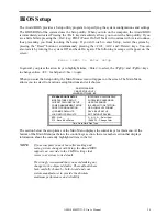
Page 20: ...creen The Main Menu allows you to select from various setup functions and exit choices ROM PCI ISA BIOS CMOS SETUP UTILITY AWARD SOFTWARE INC STANDARD CMOS SETUP INTEGRATED PERIPHERALS BIOS FEATURES SETUP SUPERVISOR PASSWORD CHIPSET FEATURES SETUP USER PASSWORD POWER MANAGEMENT SETUP IDE HDD AUTO DETECTION PNP PCI CONFIGURATION HDD LOW LEVEL FORMAT LOAD BIOS DEFAULTS SAVE EXIT SETUP LOAD SETUP DEF...

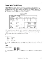
Page 21: ...y Slave None 0 0 0 0 0 0 Drive A 1 44M 3 5in Base Memory 640K Drive B None Extended Memory 15360K Floppy 3 Mode Support Disabled Other Memory 384K Video EGA VGA Halt On All Errors Total Memory 16384K ESC Quit á â à ß Select Item PU PD Modify F1 Help Shift F2 Change Color At the bottom of the menu are the control keys for use on this menu If you need any help in each item field you can press the F1...

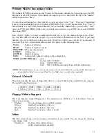
Page 22: ...entered to the following items CYLS Number of cylinders HEAD Number of read write heads PRECOMP Write precompensation LANDZ Landing zone SECTOR Number of sectors SIZE Automatically adjust according to the configuration MODE for IDE HDD only Auto Normal HD 528MB Large for MS DOS only LBA HD 528MB and supports Logical Block Addressing NOTE The specifications of your drive must match with the drive t...

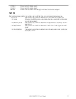
Page 23: ...stem boot will not be halted for any error that may be detected All errors Whenever the BIOS detects a non fatal error the system will be halted and you will be prompted All But Keyboard The system boot will not be halted for a keyboard error it will stop for all other errors All But Diskette The system boot will not be halted for a disk error it will stop for all other errors All But Disk Key The...

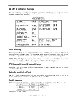
Page 24: ... BIOS Defaults Report No FDD For WIN 95 Yes F7 Load Setup Defaults Virus Warning This item protects the boot sector and partition table of your hard disk against accidental modifications If an attempt is made the BIOS will halt the system and display a warning message If this occurs you can either allow the operation to continue or run an anti virus program to locate and remove the problem NOTE Ma...

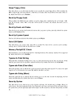
Page 25: ...st Memory Parity ECC Check This field allows you to enable the parity ECC checking function of the memory module if it is supported By default this field is set to Disabled Typematic Rate Setting When disabled continually holding down a key on your keyboard will generate only one instance When enabled you can set the two typematic controls listed next By default this field is set to Disabled Typem...

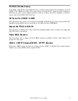
Page 26: ...tem to access greater than 64MB of DRAM memory when used with OS 2 that depends on certain BIOS calls to access memory The default setting is NON OS 2 Report No FDD For WIN 95 This option allows Windows 95 to share with other peripherals IRQ6 which is assigned to a floppy disk drive if the drive is not existing Video BIOS Shadow This item allows you to change the Video BIOS location from ROM to RA...

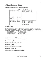
Page 27: ...olled by the DRAM Timing Registers The timing type is dependent on the system design Slower rates may be required in some system designs to support loose layouts or slower memory When set to User the following options are opened for configuration SDRAM Clock Ratio MD High Drive Control MA BA High Drive Control Control High Drive Slew Two Clock Address Setup SDCLK Edge Delay SDCLK Falling Delay SDC...

Page 28: ...K This field allows you to select the recovery time allowed for 16 bit I O 8 Bit I O Recovery CLK This field allows you to select the recovery time allowed for 8 bit I O USB Controller This field allows you to enable or disable the USB controller on board ...

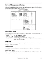
Page 29: ...F ESC Quit á â à ß Select Item F1 Help PU PD Modify F5 Old Values Shift F2 Color F6 Load BIOS Defaults F7 Load Setup Defaults Power Management This field allows you to select the type of power saving management modes There are four selections for Power Management Disable No power management Default Min Power Saving Minimum power management Max Power Saving Maximum power management Only available f...

Page 30: ...NP OS Installed Yes PCI IRQ Activated By Level Resources Controlled by Manual Reset Configuration Data Disabled Used MEM base addr N A IRQ 3 assigned to Legacy ISA IRQ 4 assigned to Legacy ISA IRQ 5 assigned to Legacy ISA IRQ 7 assigned to Legacy ISA IRQ 9 assigned to Legacy ISA IRQ 10 assigned to Legacy ISA IRQ 11 assigned to PCI ISA PnP IRQ 12 assigned to PCI ISA PnP IRQ 14 assigned to PCI ISA P...

Page 31: ...ore than one legacy ISA card in your system that require the use of this address range you can increase the block size to either 8K 16K 32K or 64K If you are using ICU to accomplish this task leave Used MEM base addr to its default setting of N A Load BIOS Defaults This option allows you to load the troubleshooting default values permanently stored in the BIOS ROM These default settings are non op...

Page 32: ...RALS AWARD SOFTWARE INC IDE HDD Block Mode Enabled Primary IDE Channel Enabled Onboard Serial Port 3 3F8H Master Drive PIO Mode Auto Serial Port 3 Use IRQ IRQ10 Slave Drive PIO Mode Auto Onboard Serial Port 4 2E8H Secondary IDE Channel Enabled Serial Port 4 Use IRQ IRQ9 Master Drive PIO Mode Auto Digital I O Index Disabled Slave Drive PIO Mode Auto IDE Primary Master UDMA Auto Build in CPU Audio E...

Page 33: ...oard controller input clock is 8 MHz Onboard FDC Controller This option allows you to select the onboard FDD port Onboard Serial Parallel Port These fields allow you to select the onboard serial parallel port and its address The default values for these ports are Serial Port 1 3F8 IRQ4 Serial Port 2 2F8 IRQ3 Serial Port 3 3E8 IRQ10 Serial Port 4 2E8 IRQ9 Parallel Port 378H IRQ7 UR2 Mode This field...

Page 34: ...0H IN DX If IN 0 1 IN 1 0 Then AX 1 Note The INPUT signal must be TTL compatible Supervisor User Password These two options set the system password Supervisor Password sets a password that will be used to protect the system and Setup utility User Password sets a password that will be used exclusively on the system To specify a password highlight the type you want and press Enter The Enter Password...

Page 35: ...ZE CYLS HEAD PRECOMP LANDZ SECTOR MODE Primary Master Select Primary Master Option N SKIP N OPTIONS TYP E SIZE CYLS HEAD PRECOMP LANDZ SECTOR MODE 1 Y 0 0 0 0 0 0 0 NORMAL NOTE Some OSes like SCO UNIX must use N ORMAL for installation Up to four IDE drives can be detected with parameters for each appearing in sequence inside a box To accept the displayed entries press the Y key to skip to the next...

Page 36: ...â à ß Select Item F10 Save Exit Setup Shift F2 Change Color Save Data to CMOS Exit Setup Exit Without Saving Select this option to exit the Setup utility without saving the changes you have made in this session Typing Y will quit the Setup utility without saving the modifications Typing N will return you to Setup utility ROM PCI ISA BIOS CMOS SETUP UTILITY AWARD SOFTWARE INC STANDARD CMOS SETUP IN...

Reviews: