E P I C B o a r d
E P I C - B D U 7
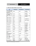
D.1 Electrical Specifications for I/O Ports
I/O
Reference
Signal Name
Rate Output
LVDS Port1/eDP
Inverter/Backlight
Connector
CN24
VDD
+5V/2A
or
+12V/2A
LVDS Port 2
Inverter/Backlight
Connector
CN36
VDD
+5V/2A
or
+12V/2A
USB 3.0 Port 1 &
2
CN30
+5VSB
+5VSB/1A (per
channel)
USB 2.0 Port 3
CN10
+5VSB
USB 2.0 Port 4
CN7
+5VSB
+5VSB/0.5A
USB 2.0 Port 5
CN11
+5VSB
(per channel)
USB 2.0 Port 6
CN37
+5VSB
Audio I/O Port
CN6
+5V
+5V/0.5A
LVDS Port 1
CN25
VCC
+3.3V/2A
or
+5V/2A
LVDS Port 2
CN32
VCC
+3.3V/2A
or
+5V/2A
COM Port 2
CN33B
+5V/+12V
+5V/1A
or
+12V/1A
COM Port 3
CN29
+5V/+12V
+5V/1A
or
+12V/1A
Digital IO Port
CN9
D0~D7
+5V/(Open
drain)
PS/2
Keyboard/Mouse
Combo Port
CN18
+5VSB
+5VSB/1A
CPU FAN
CN17
VDD
+12V/0.5A
+5V Output for
SATA HDD
CN14
+5V
+5V/1A
VGA Ports
CN34
VGA: +5V
+5V/1A
(reserved)
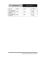
Mini-Card Slot
CN12
CN38
+3.3VSB
+1.5V
+3.3V/1.1A
+1.5V/0.375A
Appendix D Electrical Specifications for I/O Ports
D-2
Summary of Contents for EPIC-BDU7
Page 11: ...EPIC Board E P I C B D U 7 General Information Chapter 1 Chapter 1 General Information 1 1...
Page 20: ...EPIC Board E P I C B D U 7 Chapter 2 Quick Installation Guide 2 4 With Heat Spreader...
Page 73: ...EPIC Board E P I C B D U 7 AMI BIOS Setup Chapter 3 Chapter 3 AMI BIOS Setup 3 1...
Page 103: ...EPIC Board E P I C B D U 7 Set GPIO Level when used as Output Chapter 3 AMI BIOS Setup 3 31...
Page 111: ...EPIC Board E P I C B D U 7 70 80 90 100 Select Backlight Level Chapter 3 AMI BIOS Setup 3 39...
Page 117: ...EPIC Board E P I C B D U 7 The order of boot priorities Chapter 3 AMI BIOS Setup 3 45...
Page 121: ...EPIC Board E P I C B D U 7 Driver Installation Chapter 4 Chapter 4 Driver Installation 4 1...
Page 126: ...EPIC Board E P I C B D U 7 Chapter 4 Driver Installation 4 6...
Page 128: ...EPIC Board E P I C B D U 7 3 Run patch bat as administrator Chapter 4 Driver Installation 4 8...
Page 137: ...EPIC Board E P I C B D U 7 I O Information Appendix B Appendix B I O Information B 1...
Page 138: ...EPIC Board E P I C B D U 7 B 1 I O Address Map Appendix B I O Information B 2...
Page 139: ...EPIC Board E P I C B D U 7 Appendix B I O Information B 3...
Page 140: ...EPIC Board E P I C B D U 7 B 2 Memory Address Map Appendix B I O Information B 4...
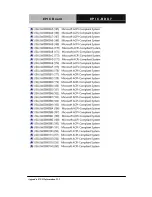
Page 141: ...EPIC Board E P I C B D U 7 B 3 IRQ Mapping Chart Appendix B I O Information B 5...
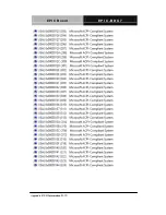
Page 142: ...EPIC Board E P I C B D U 7 Appendix B I O Information B 6...
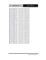
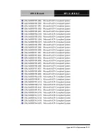
Page 143: ...EPIC Board E P I C B D U 7 Appendix B I O Information B 7...
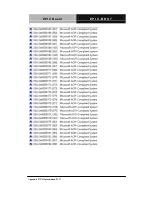
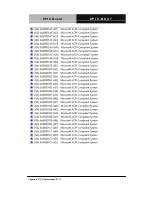
Page 144: ...EPIC Board E P I C B D U 7 Appendix B I O Information B 8...
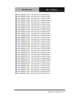
Page 145: ...EPIC Board E P I C B D U 7 Appendix B I O Information B 9...
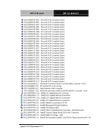
Page 146: ...EPIC Board E P I C B D U 7 Appendix B I O Information B 10...
Page 147: ...EPIC Board E P I C B D U 7 Appendix B I O Information B 11...
Page 148: ...EPIC Board E P I C B D U 7 Appendix B I O Information B 12...
Page 149: ...EPIC Board E P I C B D U 7 Appendix B I O Information B 13...
Page 150: ...EPIC Board E P I C B D U 7 Appendix B I O Information B 14...
Page 151: ...EPIC Board E P I C B D U 7 Appendix B I O Information B 15...
Page 152: ...EPIC Board E P I C B D U 7 Appendix B I O Information B 16...
Page 153: ...EPIC Board E P I C B D U 7 B 4 DMA Channel Assignments Appendix B I O Information B 17...
Page 154: ...EPIC Board E P I C B D U 7 Mating Connectors Appendix C Appendix C Mating Connector C 1...
Page 160: ...EPIC Board E P I C B D U 7 Digital I O Ports Appendix E Appendix E Digital I O Ports E 1...

