background image

P C / 1 0 4   C P U   M o d u l e  

P F M - 5 5 0 S


Chapter 2 Quick Installation Guide     


2 - 5

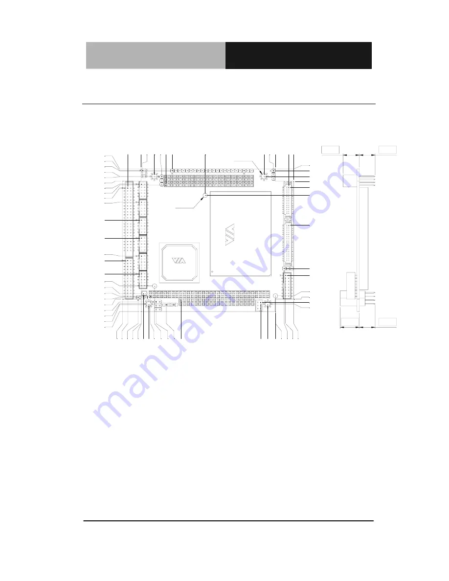
2.3 Mechanical Drawing   

Component Side   

0

.0

0

4

.9

7

1

1

.8

7

7

.1

0

1

.2

7

5

.1

1

4

.7

9

1

4

.0

7

1

7

.5

1

2

1

.5

9

7

5

.3

1

8

0

.0

1

8

5

.0

9

8

5

.2

3

9

7

.4

8

9

1

.9

8

9

1

.0

8

0.96

0.00

5.44

3.20

19.17

23.86

52.88

78.45

82.40

89.39

90.80

85.70

9

4

.1

1

8

3

.8

4

8

5

.0

9

9

7

.4

4

7

7

.4

7

1

5

.8

3

8

.7

8

1

1

.4

3

3

.8

1

4

.0

3

5

.1

1

85.70

89.74

90.80

80.43

77.88

68.37

82.50

56.30

44.24

32.17
29.13

12.05

4.43
3.20

0.00

5.10

1.38

5.08

20.24

0.55

3

7

.9

9

85.45

89.46

79.70

73.01

3

.9

5

O3.10

O3.56

11.00

10.60

12.90

10.60

6.84

3

.5

3

1

4

.0

7


Summary of Contents for PFM-550S

Page 1: ...PC 104 Module P F M 5 5 0 S PFM 550S VIA Mark Processor PC 104 CPU Module With LCD Ethernet COM USB Ports PFM 550S Manual Rev A 1st Ed FEB 2006 ...

Page 2: ... this manual is intended to be accurate and reliable However the original manufacturer assumes no responsibility for its use or for any infringements upon the rights of third parties that may result from its use The material in this document is for product information only and is subject to change without notice While reasonable efforts have been made in the preparation of this document to assure ...

Page 3: ...pactFlash is a trademark of the Compact Flash Association Intel Pentium and Celeron are trademarks of Intel Corporation Microsoft Windows is a registered trademark of Microsoft Corp IBM PC AT PS 2 and VGA are trademarks of International Business Machines Corporation Please be notified that all other products name or trademarks not be mentioned above are properties of their respective owners ...

Page 4: ...ble Kit Keyboard Mouse cable x 1 COM Port Cable x 2 VGA Cable x 1 Parallel Port Cable x 1 IDE Cable x 1 USB Port Cable x 2 Ethernet Cable x 1 1 Quick Installation Guide 1 CD ROM for manual in PDF format and drivers 1 PFM 550S CPU Module If any of these items should be missing or damaged please contact your distributor or sales representative immediately ...

Page 5: ...2 5 List of Connectors 2 8 2 6 Setting Jumpers 2 10 2 7 Clear CMOS Selection JP1 2 11 2 8 COM1 2 Ring VCC5 Selection JP2 2 11 2 9 Auxiliary Power Connector JP3 2 11 2 10 PC104 plus VIO Voltage Selection JP4 2 11 2 11 LVDS Voltage Selection JP5 2 12 2 12 TFT ODCK Normal Inverted Selection JP6 2 12 2 13 IDE Connector CN1 2 12 2 14 10 100Base TX Ethernet Connector CN3 2 13 2 15 RS 232 Serial Port Con...

Page 6: ...VGA Display Connector CN16 2 16 2 25 LVDS Connector CN17 2 16 2 26 TTL_LCD Connector CN18 2 17 Chapter 3 Award BIOS Setup 3 1 System Test and Initialization 3 2 3 2 Award BIOS Setup 3 3 Chapter 4 Driver Installation 4 1 Installation 4 3 Appendix A Programming The Watchdog Timer A 1 Programming A 2 Appendix B I O Information B 1 I O Address Map B 2 B 2 1st MB Memory Address Map B 2 B 3 IRQ Mapping ...

Page 7: ...PC 104 CPU Module P F M 5 5 0 S Chapter 1 General Information 1 1 General Chapter 1 Information ...

Page 8: ...ven long life 533MHz VIA Mark processor It includes popular embedded features such as 10 100Base TX Fast Ethernet port one RS 232 port and one RS 232 485 port USB a SDRAM SODIMM socket for up to 512 MByte is a standard feature and PC 104 Plus expansion included The PFM 550S supports 36 bit TTL 18 36 bit dual LVDS LCD panel it has a watchdog timer and is Lead free for RoHS compliance The PFM 550S f...

Page 9: ...r SODIMM SDRAM up to 512MB Supports ATA33 and CFD storage One 10 100 Base TX Fast Ethernet Supports 18 bit TTL 18 36 bit dual channel LVDS LCD Panel 4 USB1 1 ports Parallel Port 2 Serial Ports IrDA Port Supports AC97 Audio via Audio Daughter Board PC 104 Plus Socket Watchdog Timer Lead free ROHS Compliance ...

Page 10: ...BL 10 100Base TX RJ 45 connector x 1 Watchdog Timer Generates a time out system Reset 1 255 sec H W Status Monitoring VT82C686B supports power supply voltage and temperature monitoring SSD Type I CompactFlash Slot x 1 Expansion Interface PC 104 Battery Lithium battery Power Requirement AT power connector 5V only input Board Size 4 53 L x 3 78 W 115mm x 96mm Gross Weight 0 66 lb 0 3 kg Operating Te...

Page 11: ...grated on Mark 32MB frame buffer share system memory Memory size Shared system memory up to 32 MB I O MIO EIDE UDMA33 x 1 Keyboard Mouse x 1 Parallel x 1 RS 232 x 1 COM1 RS 232 485 x 1 COM2 IrDA One IrDA Tx Rx header IDE Interface P ATA 33 x 1 Audio Supports AC97 Audio via Audio Daughter Board USB Four USB 1 1 ports ...

Page 12: ...k Installation Chapter 2 Guide Notice The Quick Installation Guide is derived from Chapter 2 of user manual For other chapters and further installation instructions please refer to the user manual CD ROM that came with the product Part No 2007550S10 Printed in Taiwan FEB 2006 ...

Page 13: ...while the power is on because a sudden rush of power can damage sensitive electronic components Always ground yourself to remove any static charge before touching the board Modern electronic devices are very sensitive to static electric charges Use a grounding wrist strap at all times Place all electronic components on a static dissipative surface or in a static shielded bag when they are not in t...

Page 14: ...ule P F M 5 5 0 S Chapter 2 Quick Installation Guide 2 3 2 2 Location of Connectors and Jumpers Component Side CN1 CN2 CN3 CN4 CN5 CN6 CN7 CN8 CN9 JP1 CN12 JP4 JP5 CN17 CN18 CN16 JP6 CN11 CN13 CN20 CN15 CN10 JP3 JP2 ...

Page 15: ...PC 104 CPU Module P F M 5 5 0 S Chapter 2 Quick Installation Guide 2 4 Solder Side BIOS DIMM1 CN19 ...

Page 16: ...31 80 01 85 09 85 23 97 48 91 98 91 08 0 96 0 00 5 44 3 20 19 17 23 86 52 88 78 45 82 40 89 39 90 80 85 70 94 11 83 84 85 09 97 44 77 47 15 83 8 78 11 43 3 81 4 03 5 11 85 70 89 74 90 80 80 43 77 88 68 37 82 50 56 30 44 24 32 17 29 13 12 05 4 43 3 20 0 00 5 10 1 38 5 08 20 24 0 55 37 99 85 45 89 46 79 70 73 01 3 95 O3 10 O3 56 11 00 10 60 12 90 10 60 6 84 3 53 14 07 ...

Page 17: ...ter 2 Quick Installation Guide 2 6 Solder Side BIOS 71 75 85 70 0 00 0 00 5 44 12 42 85 70 90 80 82 50 3 20 5 10 97 49 85 23 85 09 80 01 0 00 5 11 17 51 3 20 4 90 3 81 77 47 85 09 5 11 65 07 13 42 51 67 43 92 73 01 37 99 12 05 3 95 O3 10 ...

Page 18: ... that allow you to configure your system to suit your application The table below shows the function of each jumper in the board Jumpers Label Function JP1 Clear CMOS Select JP2 COM1 2 Ring 5V Selection JP3 Auxiliary Power Connector JP4 PC104 plus VIO Voltage Selection JP5 LVDS Voltage Selection JP6 TFT ODCK Normal Inverted Selection ...

Page 19: ...n the board Connectors Label Function CN1 IDE Connector CN2 LPT PORT Connector CN3 10 100 Base TX Ethernet Connector CN4 RS 232 Serial Port Connector CN5 RS 232 485 Serial Port Connector CN6 Audio Connector CN7 USB2 Connector CN8 USB1 Connector CN9 Battery Connector CN10 AT Power Connector CN11 PC104 Connector CN12 PC 104 Connector CN13 Front Panel Connector CN15 Key Board Mouse Connector CN16 VGA...

Page 20: ...PC 104 CPU Module P F M 5 5 0 S Chapter 2 Quick Installation Guide 2 9 CN19 CompactFlash Slot DIMM1 SODIMM Slot ...

Page 21: ...t them To close a jumper you connect the pins with the clip To open a jumper you remove the clip Sometimes a jumper will have three pins labeled 1 2 and 3 In this case you would connect either pins 1 and 2 or 2 and 3 1 2 3 Open Closed Closed 2 3 A pair of needle nose pliers may be helpful when working with jumpers If you have any doubts about the best hardware configuration for your application co...

Page 22: ... Function 1 2 Protected Defaults 2 3 Clear 2 8 COM1 2 Ring VCC5 Selection JP2 JP2 Function 1 3 5V COM1 3 5 RING COM1 Defaults 2 4 5V COM2 4 6 RING COM2 Defaults 2 9 Auxiliary Power Connector JP3 JP3 Function 1 2 12V 3 6 GND 4 12V 5 5V 2 10 PC104 plus VIO Voltage Selection JP4 JP4 Function 1 2 5V 2 3 3 3V ...

Page 23: ...3V 2 12 TFT ODCK Normal Inverted Selection JP6 JP6 Function 1 2 FPCLK Inverted Output 2 3 FPCLK Normal Output 2 13 IDE Connector CN1 Pin Signal Pin Signal 1 IDE RESET 2 GND 3 D7 4 D8 5 D6 6 D9 7 D5 8 D10 9 D4 10 D11 11 D3 12 D12 13 D2 14 D13 15 D1 16 D14 17 D0 18 D15 19 GND 20 N C 21 HPDREQ 22 GND 23 HPDIOW 24 GND 25 HPDIOR 26 GND ...

Page 24: ...5 HPDA0 36 HPDA2 37 HPCS1 38 HPCS3 39 DASP0 40 GND 41 5V 42 5V 43 GND 44 N C 2 14 10 100Base TX Ethernet Connector CN3 Pin Signal Pin Signal 1 RX 1 2 RX 1 3 C GND 4 C GND 5 LAN_GND 6 LAN_GND 7 C GND 8 C GND 9 TX 1 10 TX 1 2 15 RS 232 Serial Port Connector CN4 Pin Signal Pin Signal 1 DCD 2 SIN 3 SOUT 4 DTR 5 GND 6 DSR 7 RTS 8 CTS 9 RI 5V 10 N C ...

Page 25: ...n Signal Pin Signal 1 DCD 2 SIN 3 SOUT 4 DTR 5 GND 6 DSR 7 RTS 8 CTS 9 RI 5V 10 N C 2 17 Audio Connector CN6 Pin Signal Pin Signal 1 AC RST 2 AC SYNC 3 SDIN 4 SDOUT 5 GND 6 BITCLK 7 GND 8 5V 9 N C 10 3 3V 2 18 USB2 Connector CN7 Pin Signal Pin Signal 1 5V 2 GND 3 USBD2 4 GND 5 USBD2 6 USBD3 7 GND 8 USBD3 9 GND 10 5V ...

Page 26: ... USBD1 7 GND 8 USBD1 9 GND 10 5V 2 20 Battery Connector CN9 Pin Signal Pin Signal 1 3V 2 GND 2 21 AT Power Connector CN10 Pin Signal Pin Signal 1 5V 2 GND 2 22 Front Panel Connector CN13 Pin Signal Pin Signal 1 PWRLED 2 PWRLED 3 SPK 4 SPK 5 IDELED 6 IDELED 7 RESET 8 RESET 9 SPEED LED 10 SPEED LED 11 ACTIVE LED 12 ACTIVE LED 13 VCC 14 N C 15 IRRX 16 GND ...

Page 27: ...N15 Pin Signal Pin Signal 1 KB DATA 2 KB CLK 3 GND 4 5V 5 MS_DATA 6 MS_CLK 2 24 VGA Display Connector CN16 Pin Signal Pin Signal 1 RED 2 VGAVCC 3 GREEN 4 GND 5 BLUE 6 N C 7 N C 8 SDATA 9 GND 10 HS 11 GND 12 VS 13 GND 14 SCLK 15 GND 16 N C 2 25 LVDS Connector CN17 Pin Signal Pin Signal 1 ENVDD 2 N C 3 PPVCC 4 GND 5 LVDS_CH1_TXCLK 6 LVDS_CH1_TXCLK ...

Page 28: ...2_TX0 20 LVDS_CH2_TX0 21 LVDS_CH2_TX1 22 LVDS_CH2_TX1 23 LVDS_CH2_TX2 24 LVDS_CH2_TX2 25 N C 26 N C 27 PPVCC 28 GND 29 LVDS_CH2_TXCLK 30 LVDS_CH2_TXCLK 2 26 TTL_LCD Connector CN18 Pin Signal Pin Signal 1 5V 2 5V 3 GND 4 GND 5 3 3V 6 3 3V 7 ENBKL 8 GND 9 N C 10 N C 11 E_BLUE0 12 E_BLUE1 13 E_BLUE2 14 E_BLUE3 15 E_BLUE4 16 E_BLUE5 17 N C 18 N C 19 E_GREEN0 20 E_GREEN1 21 E_GREEN2 22 E_GREEN3 23 E_GR...

Page 29: ...PC 104 CPU Module P F M 5 5 0 S Chapter 2 Quick Installation Guide 2 18 27 E_RED0 28 E_RED1 29 E_RED2 30 E_RED3 31 E_RED4 32 E_RED5 33 GND 34 GND 35 DOT_CLOCK 36 VSYNC 37 DE 38 HSYNC 39 N C 40 ENAEE ...

Page 30: ...PC 104 CPU Module P F M 5 5 0 S Chapter 3 Award BIOS Setup 3 1 Chapter Award 3 BIOS Setup ...

Page 31: ...the F1 key to continue the boot up sequence System configuration verification These routines check the current system configuration against the values stored in the CMOS memory If they do not match the program outputs an error message You will then need to run the BIOS setup program to set the configuration information in memory There are three situations in which you will need to change the CMOS ...

Page 32: ...ion is stored in battery backed CMOS RAM so that it retains the Setup information when the power is turned off Entering Setup Power on the computer and press Del immediately This will allow you to enter Setup Standard CMOS Features Use this menu for basic system configuration Date time IDE etc Advanced BIOS Features Use this menu to set the advanced features available on your system Advanced Chips...

Page 33: ...ower down power on by ring KB wake up etc PnP PCI Configurations This entry appears if your system supports PnP PCI PC Health Status This menu allows you to set the shutdown temperature for your system Frequency Voltage Control Use this menu to specify your settings for auto detect DIMM PCI clock and spread spectrum Load Fail Safe Defaults Use this menu to load the BIOS default values for the mini...

Page 34: ...nge these defaults to meet their needs Set Supervisor User Password Use this menu to set Supervisor User Passwords Save and Exit Setup Save CMOS value changes to CMOS and exit setup Exit Without Saving Abandon all CMOS value changes and exit setup You can refer to the AAEON BIOS Item Description pdf file in the CD for the meaning of each setting in this chapter ...

Page 35: ...PC 104 CPU Module P F M 5 5 0 S Chapter 4 Driver Installation 4 1 Chapter Driver 4 Installation ...

Page 36: ...hat you need for setup the system Follow the sequence below to install the drivers Step 1 Install VIA 4 in 1 Driver Step 2 Install Ethernet Driver Step 3 Install VGA Driver Insert the PFM 550S CD ROM into the CD ROM Drive And install the drivers from Step 1 to Step 3 in order Please read instructions below for further detailed installations ...

Page 37: ...n1455v file 2 Follow the instructions that the window will show you 3 The system will help you to install the driver automatically Step 2 Install Ethernet Driver for Windows 98SE 2000 XP 1 Double click on the Setup file 2 Follow the instructions that the window shows you 3 The system will help you install the driver automatically Step 3 Install VGA Driver for Windows 98SE 2000 XP 1 Double click on...

Page 38: ...PC 104 CPU Module P F M 5 5 0 S Appendix A Programming the Watchdog Timer A 1 Programming the Appendix A Watchdog Timer ...

Page 39: ...RQ10 3 IRQ11 4 IRQ15 If you decide to program the watchdog timer you must write data to I O port 443 hex The output data is a value timer You can write form 01 hex to FF hex while simultaneously setting it When you want to disable the watchdog timer your program should read a Hex value from I O port 80 hex The following procesude is a sample program for the watchdog timer Type C DOS Debug ENTER To...

Page 40: ...PC 104 CPU Module P F M 5 5 0 S Appendix B I O Information B 1 I O Information Appendix B ...

Page 41: ...rrupt Mask 070 073 080 09F DMA Page Register 080 08F 0A0 0BF Interrupt Controller 2 0A0 0A1 0C0 0DF DMA Controller 2 0C0 0DF 0F0 0FF Math Coprpcessor 0F0 0FF 170 177 Secondary IDE Channel 170 177 1F0 1F7 Primary IDE Channel 1F0 1F7 2F8 2FF Serial Port 2 2F8 2FF 378 37F Parallel Printer Port 1 378 37F 3B0 3DF EGA VGA card 3B0 3DF 3F8 3FF Serial Port 1 3F8 3FF B 2 1st MB Memory Address Map Memory Ad...

Page 42: ...Q9 Unused IRQ2 Cascade to IRQ Controller IRQ10 Unused IRQ3 COM2 IRQ11 Unused IRQ4 COM1 IRQ12 PS 2 mouse IRQ5 Unused IRQ13 FPU IRQ6 Unused IRQ14 Primary IDE IRQ7 Printer IRQ15 Secondary IDE B 4 DMA Channel Assignments DMA Channel Function 0 Available 1 Available 2 Unused 3 Available 4 Direct Memory Access Controller 5 Available 6 Available 7 Available ...

Reviews: