Chapter 2 – Hardware Information
17
IO
T G
at
eway
S
ystem
SRG
-IMX8
P
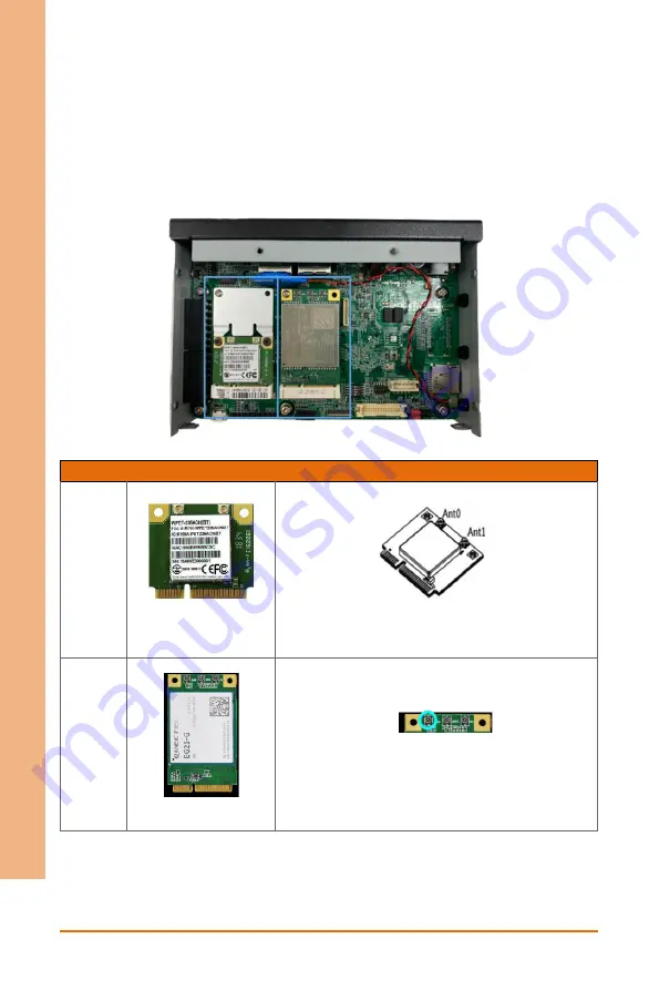
Step 4: Install Mini Card
Insert the 4G/LTE, or Wi-Fi/BT module into the slot and connect the RF coaxial cable
to the module.
Note: The installation slots are the same as the photo.
Item
Module
Installation Location
Wi-Fi
WPET-236ACN(BT)
module
Install the RF cable to left conn. to support Wi-Fi
signal.
(ANT0 for WLAN only, ANT1 for WLAN+BT)
4G/LTE
EG25-G module
Install the RF cable to left conn. to support 4G/LTE
signal
.
Step 5: Replace top cover and secure by fastening the top screws first, then the sides.
Summary of Contents for SRG-IMX8P
Page 1: ...SRG IMX8P IOT Gateway System User s Manual 1st Ed...
Page 13: ...IOT Gateway System SRG IMX8P Chapter 1 Chapter 1 Product Specifications...
Page 16: ...IOT Gateway System SRG IMX8P Chapter 2 Chapter 2 Hardware Information...
Page 17: ...Chapter 2 Hardware Information 5 IOT Gateway System SRG IMX8P 2 1 Dimensions...
Page 18: ...Chapter 2 Hardware Information 6 IOT Gateway System SRG IMX8P 2 2 I O Location...
Page 31: ...IOT Gateway System SRG IMX8P Chapter 3 Chapter 3 Gateway Setup and Configuration...


