E m b e d d e d B o x
T K S - G 5 0 - Q M 7 7
Appendix C Mating Connector
C - 2
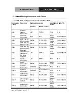
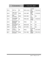
C.1 List of Mating Connectors and Cables
The table notes mating connectors and available cables.
Mating Connector
Connector
Label
Function
Vendor Model
number
Available
Cable
Cable P/N
CN1
LVDS#1
Inverter
Connector
JST PHR-5 N/A
N/A
CN2
+12V Vin
Connector
N/A N/A
Power
Cable
1702002010
CN3
USB Port #7,
#8 Connector
Molex 51110-1050
USB
Cable
1709100201
CN4
USB Port #5,
#6 Connector
Molex 51110-1050
USB
Cable
1709100201
CN5
USB Port #3,
#4 Connector
Molex 51110-1050
USB
Cable
1709100201
CN6
External
+5VSB Power
Input and
PS_ON#
JST XHP-3
ATX
Cable
170220020B
CN7
LVDS#2
Inverter
Connector
JST PHR-5 N/A
N/A
CN8
Audio
Connector
Molex 51021-1000
Audio
Cable
1709100254
CN9
LVDS#1
Connector
HIROSE
DF13-30DS-1.2
5C
N/A N/A
CN10
LVDS#2
Connector
HIROSE
DF13-30DS-1.2
5C
N/A N/A
CN11
COM Port 2
Connector
Molex 51021-0900
Serial
Port
Cable
1701090150
CN12
LPT / Digital
IO Port
Molex 51110-2650
Parallel
Port
Cable
1701260200
CN13
COM Port 3
Connector
Molex 51021-0900
Serial
Port
Cable
1701090150
Summary of Contents for TKS-G50-QM77
Page 38: ...Embedded Box T K S G 5 0 Q M 7 7 Chapter 3 AMI BIOS Setup 3 1 AMI Chapter 3 BIOS Setup...
Page 98: ...Embedded Box T K S G 5 0 Q M 7 7 Appendix B I O Information B 1 I O Information Appendix B...
Page 99: ...SubCompact Board T K S G 5 0 Q M 7 7 Appendix B I O Information B 2 B 1 I O Address Map...
Page 100: ...Embedded Box T K S G 5 0 Q M 7 7 Appendix B I O Information B 3...
Page 101: ...SubCompact Board T K S G 5 0 Q M 7 7 Appendix B I O Information B 4 B 2 Memory Address Map...
Page 103: ...Embedded Box T K S G 5 0 Q M 7 7 Appendix C Mating Connector C 1 Mating Connector Appendix C...
Page 106: ...Embedded Box T K S G 5 0 Q M 7 7 Appendix D AHCI Setting D 1 AHCI Setting Appendix D...
Page 110: ...Embedded Box T K S G 5 0 Q M 7 7 AppendixE Digital I O Ports E 1 Digital I O Ports Appendix E...

