E m b e d d e d B o x
T K S - G 5 0 - Q M 7 7
AppendixE Digital I/O Ports
E - 2
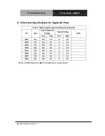
E.1 Electrical Specifications for Digital I/O Ports
Table
1
:
Digital
Input/Output
Pin
Electrical
Specification
Input
Threshold
Voltage
Output
Voltage
Pin
Type
Low
High
Low
High
Note
DIO1
I/O
0.8
2.2
0
3.3
DIO2
I/O
0.8
2.2
0
3.3
DIO3
I/O
0.8
2.2
0
3.3
DIO4
I/O
0.8
2.2
0
3.3
DIO5
I/O
0.8
2.2
0
3.3
DIO6
I/O
0.8
2.2
0
3.3
DIO7
I/O
0.8
2.2
0
3.3
DIO8
I/O
0.8
2.2
0
3.3
Note: All DIO pins are
not
5V tolerance in input mode.
Summary of Contents for TKS-G50-QM77
Page 38: ...Embedded Box T K S G 5 0 Q M 7 7 Chapter 3 AMI BIOS Setup 3 1 AMI Chapter 3 BIOS Setup...
Page 98: ...Embedded Box T K S G 5 0 Q M 7 7 Appendix B I O Information B 1 I O Information Appendix B...
Page 99: ...SubCompact Board T K S G 5 0 Q M 7 7 Appendix B I O Information B 2 B 1 I O Address Map...
Page 100: ...Embedded Box T K S G 5 0 Q M 7 7 Appendix B I O Information B 3...
Page 101: ...SubCompact Board T K S G 5 0 Q M 7 7 Appendix B I O Information B 4 B 2 Memory Address Map...
Page 103: ...Embedded Box T K S G 5 0 Q M 7 7 Appendix C Mating Connector C 1 Mating Connector Appendix C...
Page 106: ...Embedded Box T K S G 5 0 Q M 7 7 Appendix D AHCI Setting D 1 AHCI Setting Appendix D...
Page 110: ...Embedded Box T K S G 5 0 Q M 7 7 AppendixE Digital I O Ports E 1 Digital I O Ports Appendix E...

