background image

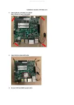
Installation Guide For UP Xtreme i11 

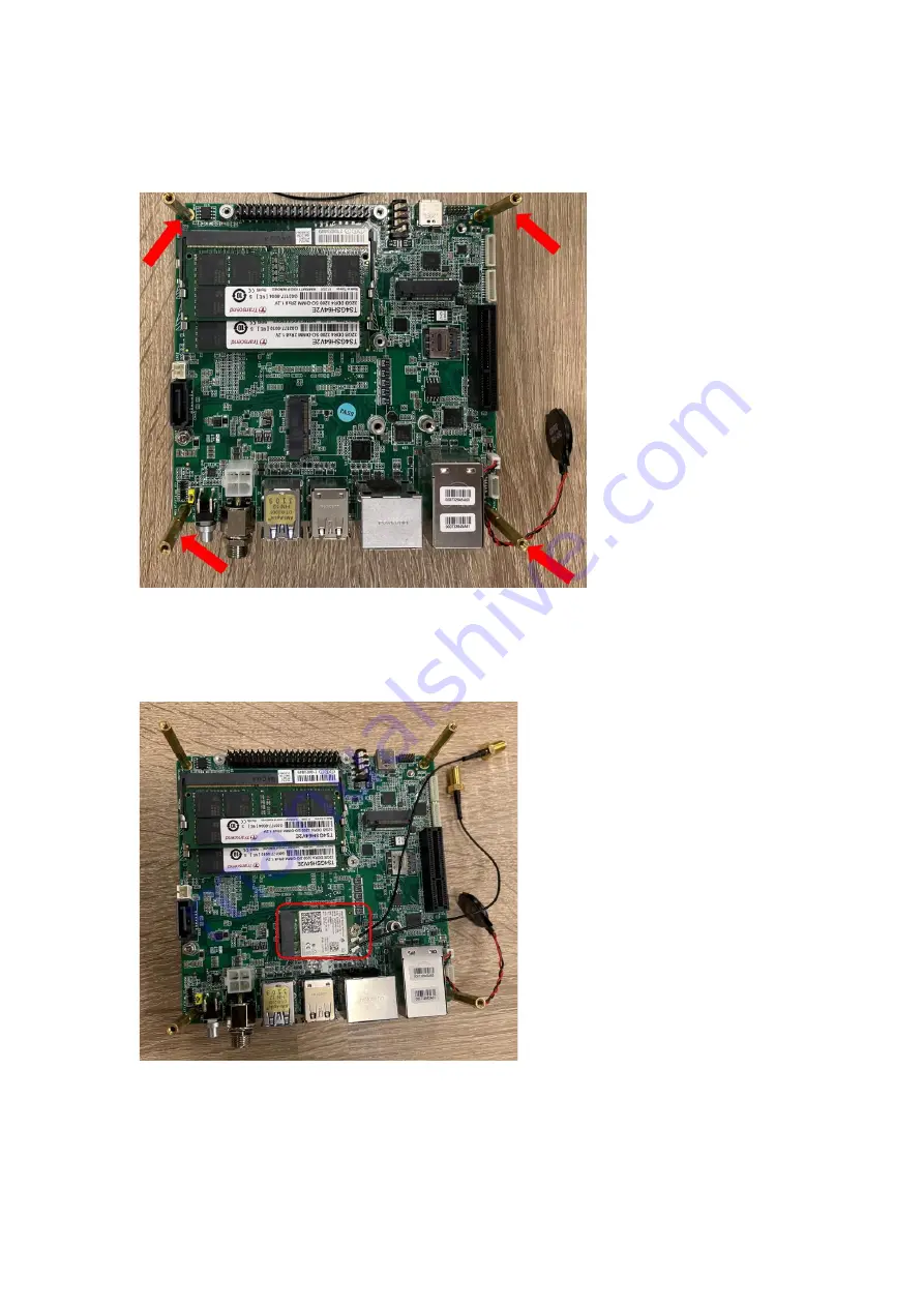
1.


Install pillars to UP Xtreme i11 board 
Need: 4pcs m2.5 nuts, 4pcs pillars 


2.


Install Wi-Fi module & RF cable 


3.


Connect SATA and SATA power cable 

All manuals and user guides at all-guidesbox.com

Summary of Contents for UP Xtreme i11

Page 1: ...eme i11 Mecanum Robot plates Motor Bracket x 4 motors x 4 Wheels x 4 Motor control board ST link V2 Cables x 4 Micro USB cable screw set screw set screw set screw set 60w 12V 5A power adapter For motor wheel assemble for bracket motor assemble for board camera SSD assemble for top plastic plate for motor control board motor control board assemble All manuals and user guides at all guidesbox com a ...

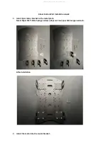
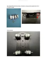
Page 2: ...uide 1 Install 4pcs motor bracket to the metal plate Need 16pcs M3 10mm hexagon screws 16pcs m3 nut 1pcs M3 hexagon wrench After Installation 2 Install the motor into the motor bracket All manuals and user guides at all guidesbox com ...

Page 3: ...Need 24pcs M3 6mm flat head screws Follow the same way as below right picture to fix t he motor to bracket After Installation All manuals and user guides at all guidesbox com ...

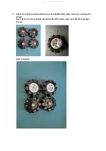
Page 4: ...the wheel and use the M3x8mm flat head screw to fix coupling with wheels Need 4pcs inner size couplings 4pcs M2 5 8mm flat head screws 4pcs M3 6mm hexagon screws After Installation All manuals and user guides at all guidesbox com ...

Page 5: ... into the motor Note that the coupling is screwed onto the concave end of the motor After Installation Note the installation direction of the wheels as shown in the picture All manuals and user guides at all guidesbox com ...

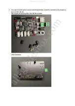
Page 6: ...or control board before install the controller on the chassis to prevent short circuits Need 4pcs short plastic pillars 4pcs M3 6mm screws After Installation All manuals and user guides at all guidesbox com a l l g u i d e s b o x c o m ...

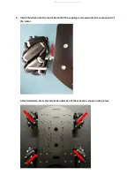
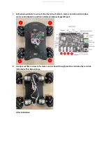
Page 7: ...6 Assemble 4pcs cables to motor control board a Connect 4 cables to 4 Motors b Pass the cable through the hole indicated in below picture All manuals and user guides at all guidesbox com ...

Page 8: ...l board and place motor control board in position indicated in below image left part 8 Use 4pcs m3 8mm screw to fix motor control board through locations indicated by red circle indicated within below image After Installation All manuals and user guides at all guidesbox com ...

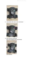
Page 9: ...9 Assemble Micro USB cable to motor control board 10 Install long pillar to metal plate Need 4pcs Long plastic pillar 4pcs m3 8screw After installation All manuals and user guides at all guidesbox com ...

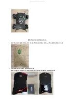
Page 10: ... plastic plate It depends on you if remove sticker on top of the plastic plate or not 2 Install RealSense D435i Camera and SSD Need 1 pcs screw for realsense camera and 2pcs m3 8mm screws for SSD All manuals and user guides at all guidesbox com ...

Page 11: ...After Installation 3 Assemble SSD cables All manuals and user guides at all guidesbox com a l l g u i d e s b o x c o m ...

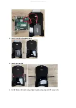
Page 12: ...Guide For UP Xtreme i11 1 Install pillars to UP Xtreme i11 board Need 4pcs m2 5 nuts 4pcs pillars 2 Install Wi Fi module RF cable 3 Connect SATA and SATA power cable All manuals and user guides at all guidesbox com ...

Page 13: ...4 Install RF cable to top plastic plate 5 Install the antennas 6 Put UP Xtreme i11 board on top of plastic plate and use 4pcs m2 5 8 screw to fix All manuals and user guides at all guidesbox com ...

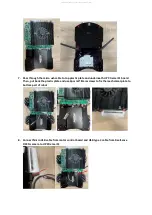
Page 14: ...1 board Then put back the plastic plate and use 4pcs m3 8mm screws to fix the mechanical plate to bottom part of robot 8 Connect Micro USB cable from motor control board and USB type C cable from RealSense D435i camera to UP Xtreme i11 All manuals and user guides at all guidesbox com ...

Page 15: ...9 Power UP Through power adapter i Power adapter for UP Xtreme i11 96W 12V 8A ii Power adapter for Motor Control Board 60W 12V 5A All manuals and user guides at all guidesbox com ...

Reviews: