19
NOTE: Actual content of the OLED screen may vary depending on
the model and device confi guration.
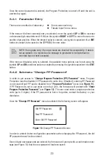
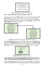
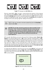
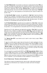
The main DPC fl ow controller screen shows current instrument Absolute Pressure,
Temperature, Mass Flow reading, Set Point Value, Set Point Source and Valve Mode.
NOTE: 5 seconds after the initial powering of the DPC controller, the status LED
will emit a constant GREEN light (normal operation, ready to control).
By default, unless
“Local Set Point Auto Start"
parameter is enabled (see
Section 6.4.3
),
after power is applied to the instrument the controller’s
Valve Mode
set to
“Closed”
. In this
mode regardless of the
“Set Point Source”
and
“Set Point Value”
parameters settings, the
valve will be closed and fl ow rate through the instrument will be zero.
NOTE: On power up, the last used
Set Point
Source settings will be retrieved
from the instrument’s non-volatile memory and set as active.
6.2 Swamping
Condition
If a fl ow of more than 133% the nominal maximum fl ow rate of the Mass Flow Controller
is taking place (displayed mass fl ow reading is fl ashing), a condition known as "swamping"
may occur. Readings of a "swamped" instrument cannot be assumed to be either accurate or
linear. Flow must be restored to below 133% of full scale range. Once fl ow rates are lowered
to within calibrated range, the swamping condition will end.
6.3
Instrument Process Information (PI) screens
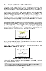
Based on instrument confi guration, different parameters may be displayed in the Process
Information (PI) screen by moving the control joystick (see
Figure 9
)
Up or Down (DN).
FIGURE 9:
Control Joystick
Process Information screens can be confi gured to be static or dynamic (see
Section 6.4.15.3
“Display and Process Information (PI) Screens”
). Using PI Screen Mask settings, the user
can enable (unmask) or disable (mask) up to 8 different process information combinations.
Summary of Contents for DPC
Page 6: ...2...
Page 120: ...116 APPENDIX I COMPONENT DIAGRAM Top Component Side...
Page 121: ...117 Bottom Component Side...

