the top of the valve will indicate a fully OPEN valve condition.
During normal operation the valve remains in the last position as it is de-
energized. After powering up, the valve will be automatically closed with-
in the first 10 seconds and after that resumes control operation.
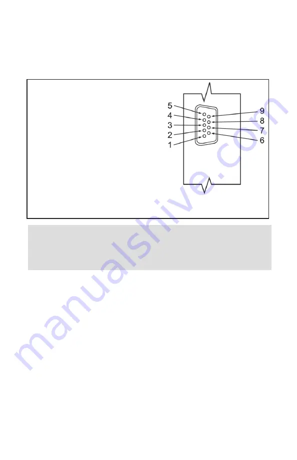
FIG.b-1
SMV 9-PIN “D” CONNECTOR CONFIGURATION
WARNING
: DO NOT CONNECT 24 Vdc POWER SUPPLY UNLESS YOUR
SMV VALVE WAS ORDERED AND CONFIGURED FOR 24Vdc VOLTAGE
(SEE POWER REQUIREMENTS LABEL). DO NOT APPLY TO THE
DIRECTION CONTROL SIGNAL (PIN 8) VOLTAGE MORE THAN 12 Vdc
Important Notes:
In general, "D" Connector numbering patterns are standardized. There
are, however, some connectors with nonconforming patterns and the
numbering sequence on your mating connector may or may not coincide
with the numbering sequence shown in our pin configuration table above.
It is imperative that you match the appropriate wires in accordance with
the correct sequence regardless of the particular numbers displayed on
your mating connector.
Make sure power is OFF when connecting or disconnecting any cables in
the system.
The power input is protected by a 1600mA M (medium time-lag) reset-
table fuse. If a shorting condition or polarity reversal occurs, the fuse will
cut power to the valve circuit. Disconnect the power to the unit, remove
the faulty condition, and reconnect the power.
3
,
PIN FUNCTION
1
(unassigned).
2
Common, Power Supply Minus.
3
Valve Off Control (12V CMOS Low active).
4
Speed control signal (analog 0-2.5 Vdc).
5
(unassigned).
6
Common for Speed control.
7
Valve PURGE control (12V CMOS Low Active).
8
Direction control signal (digital 12Vdc CMOS logic).
9
+12 Vdc (+24Vdc optional) Power Supply Plus.


