3-1
3
.
BEFORE MEASURING
3.1 Cable Connections
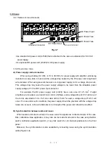
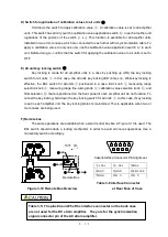
3.1.1 Input Cable Connections (See Figure 3-1.)
(1) Paste a strain gauge to the location where measurement is made.
(2) Connect the strain gauge to the bridge box.
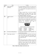
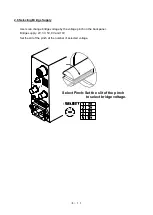
(3) Adjust the power supply for strain gauge with bridge power voltage selection switch 2 . Set the
supply voltage to 2 V for general 120-ohm strain gauge. When using a transducer, set to 3 V, 5 V,
9 V, or 10 V according to the input voltage. For details see page 4-7, Measurement Using
Transducer.
(4) Connect the bridge box or a transducer to the input connector 2 on the rear panel. For
connection information, see Cautions before Measuring on page 4-1. Since the AS2503 and
AS2603 automatically adjust the voltage drop generated between the bridge and the amplifier
through the wire length adjustment function, high-accuracy measurement is possible. For more
information on this adjustment function, see page 3-6.
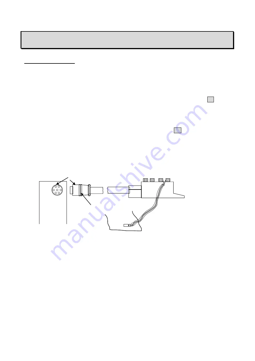
Figure 3-1 Connection with bridge box and so on
Bridge Box
When you yank this plug out of
the connector, you must hold
this part without rotating it.
Rear Panel
Input Connector
Use a strain gauge with short wires between
the measuring point and the bridge box in
order to reduce noise as much as possible.
Do not cut or add wire as the strain
gauge
performs gauge factor calibration with the
wires connected.
Mark
Summary of Contents for AS2503
Page 1: ...AS2503 AS2603 DC BRIDGE SYSTEM DYNAMIC STRAIN AMPLIFIERS INSTRUCTION MANUAL 1WMPD4003356 ...
Page 2: ......
Page 4: ......
Page 30: ......
Page 46: ......
Page 68: ......
Page 83: ...9 5 9 3 External Dimensions 9 3 1 Amplifier Unit AS2503 ...
Page 84: ...9 6 9 3 2 Amplifier Unit AS2603 ...
Page 85: ...9 7 9 3 3 Panel Cut Sizes ...
Page 87: ...9 9 9 3 5 Rack mount Case Rack Rail Elongate Hole ...


