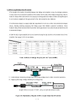
3-2
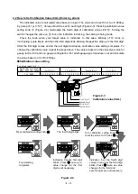
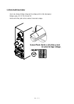
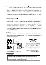
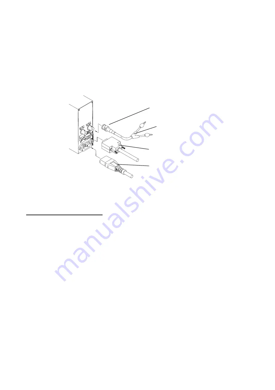
3.1.2 Power Supply Cable and Output Cable Connections (See Figure 3-2)
(1) Use the power supply cable for 100 VAC (Model 0311-5112 for 110 VAC or higher), 200 VAC, or
12 VDC depending on the voltage.
(2) Connect the output cable appropriate to the recorder to be used.
(3) For more information, refer to Connection between Output and Load on page 4-12.
(4) The chassis of this amplifier is connected to the output common lead.
Figure 3-2 Connection of power supply code and output cable
3.2 Operation before Measuring
3.2.1 Standalone Operation
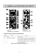
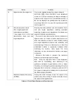
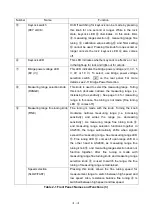
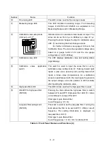
(1) Set the calibration value application switch
⑭
(+
-) to the
(OFF) position.
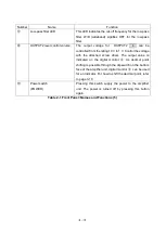
(2) Pressing power switch
⑲
(POWER) supplies power to the amplifier.
(3) Set the measuring range to OFF (Measuring Range LED
⑪
) using measuring range selection
knob
⑧
(RANGE).
(4) Setting the measuring range to OFF using measuring range selection knob
⑧
illuminates the
green LED in the middle of level meter
②
. Activate for about 10 minutes.
(5) For correct strain measurement, you must conduct initial balancing for the bridge circuit. Tune
to your target measuring range using measuring range selection knob
⑧
and adjust the
output to zero while no load is being applied.
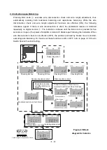
(6) Wire disconnection check, wire length adjustment, and automatic balancing.
Turn measuring range selection knob
⑧
clockwise up to your target measuring range,
and then narrow the measuring range (i.e. increasing sensitivity). In this case, the indication of
measuring range LED
⑪
changes from OFF to other values, in that the value changes toward
200. Pressing the BAL knob
④
performs the wire disconnection check, wire length
adjustment (indication of the rate of damping), and auto-balancing in this order. For more
information, see Indication upon Execution of BAL on page 2-7.
Cable for OUTPUT1.2
(
0311-2057
)
DC supply cable or
SYNC cable
AC power supply cable
You can lock the cable
by turning for 45
clockwise.
100 VAC power supply: 47326,
200 VAC power supply: 0311-5112)
Summary of Contents for AS2503
Page 1: ...AS2503 AS2603 DC BRIDGE SYSTEM DYNAMIC STRAIN AMPLIFIERS INSTRUCTION MANUAL 1WMPD4003356 ...
Page 2: ......
Page 4: ......
Page 30: ......
Page 46: ......
Page 68: ......
Page 83: ...9 5 9 3 External Dimensions 9 3 1 Amplifier Unit AS2503 ...
Page 84: ...9 6 9 3 2 Amplifier Unit AS2603 ...
Page 85: ...9 7 9 3 3 Panel Cut Sizes ...
Page 87: ...9 9 9 3 5 Rack mount Case Rack Rail Elongate Hole ...

