3-13
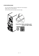
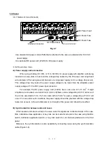
D) Switch for application of calibration values to all units
②
Hold down the switch to apply calibration value
②
. A calibration value is set to all amplifier
units. This switch has priority over the calibration value application switch
⑭
in each amplifier unit
regardless of the position of the switch (+
-). This function is available for all amplifier units
installed in two or more cases, which are connected to each other with a synchronization cable. To
apply a calibration value to only one unit, use the calibration value application switch
⑭
in each
unit. Before doing so, confirm that the switch for applying the calibration value to all units is set to
OFF.
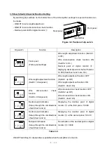
E) All unit key locking switch
③
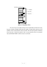
Key locking is made for all amplifier units in a case by pushing up (ON) the key locking
switch for all units
③
. In this case, the all units key locking LED comes on. While key locking is
effective, the BAL switch for all units
①
positioned in a case, BAL knob
④
, measuring range
selection knob
⑧
, measuring range fine-tuning knob
⑨
, calibration value selection knob
⑫
, and
filter selection
⑯
that are positioned on the front panel of each amplifier unit do not function. To
cancel the key locking, hold down the key locking switch for all units
③
. In this case, if key locking
is set in each amplifier unit, the key locking status is maintained. This is applicable when two or
more cases are being used.
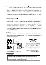
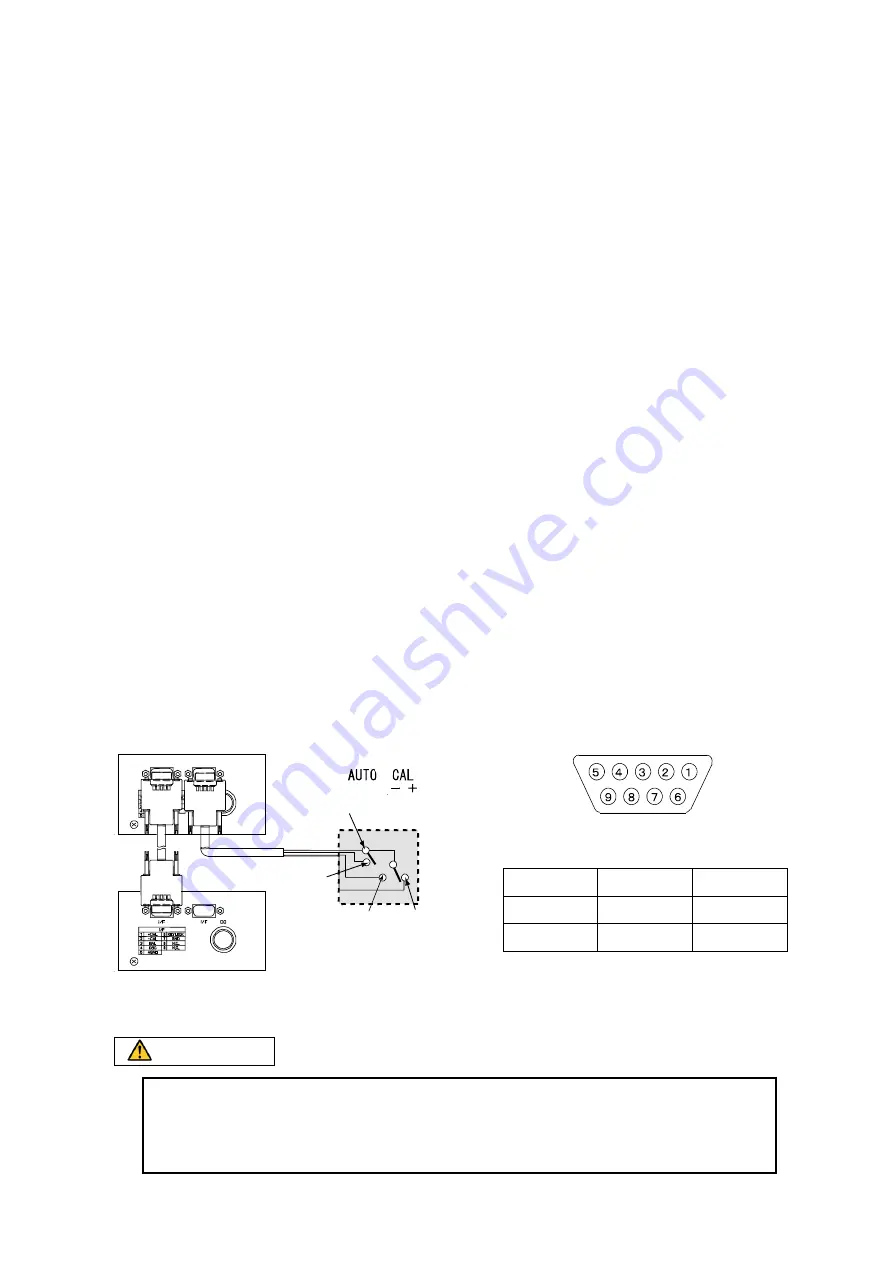
F) Remote box
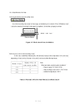
The same operations are available when a small control box like in Figure 3-10 is used. The
BAL switch should include a locking mechanism in order to avoid erroneous operations. Use a
momentary switch accordingly.
Case/Interface Connector Pin Alignment
Remote Box
Figure 3-10 Remote Box Overview
⑦
GND
②
CAL
-
③
BAL
①
CAL
+
Table 3-6 Interface Connector
at Rear Face of Case
①+CAL
②-CAL
③BAL
④OSC
⑤GND
⑥KEYLOCK
⑦GND
⑧N.C
⑨N.C
CAUTION
Table 3-5: The pins #4 and #5 of the interface connector on the back case
are not used for the DC strain amplifier. They are for the synchronization
signal connector pin of the AC strain amplifier.
Summary of Contents for AS2503
Page 1: ...AS2503 AS2603 DC BRIDGE SYSTEM DYNAMIC STRAIN AMPLIFIERS INSTRUCTION MANUAL 1WMPD4003356 ...
Page 2: ......
Page 4: ......
Page 30: ......
Page 46: ......
Page 68: ......
Page 83: ...9 5 9 3 External Dimensions 9 3 1 Amplifier Unit AS2503 ...
Page 84: ...9 6 9 3 2 Amplifier Unit AS2603 ...
Page 85: ...9 7 9 3 3 Panel Cut Sizes ...
Page 87: ...9 9 9 3 5 Rack mount Case Rack Rail Elongate Hole ...

