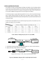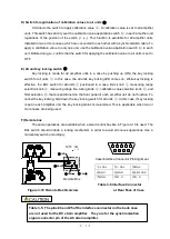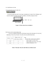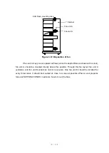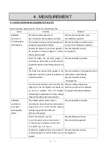
4-6
4.2.2 Bridge Box
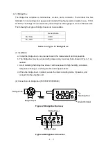
The bridge box comprises a terminal box, a cable, and a connector. The terminal box has
terminals for connecting strain gauges and contains three high-precision resisters (e.g., 120
for 5370). The bridge circuit is formed by connecting one strain gauge or more to the terminals.
The following four types of bridge boxes are now available.
General-size
For 120-
5370
For 350-
5373
Table 4-3 Type of Bridge Box
(1) Installation
a. Install the bridge box in an area as close to the measurement point as possible.
b. The bridge box may be secured with screws using the screw holes shown in Fig. 4-1, as
needed.
c. Avoid installing the bridge box where it will be exposed to high humidity, excessive
temperature changes, or strong electric and magnetic fields.
d. When the bridge box is installed, secure the interconnecting cable, if possible, and
connect it to the amplifier unit.
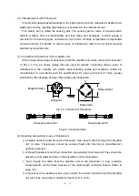
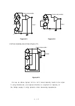
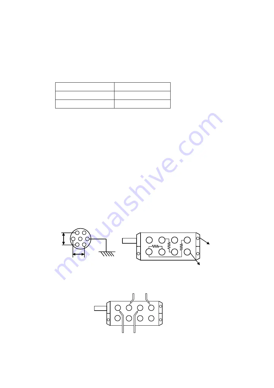
(2) Connections to bridge box (5370/5373/5379/5380)
A
E
B
C
D
B
C
E
D
A
Bridge Power
A
E
B
C
D
Bridge Output
Mounting Hole
Ground Terminal
Bridge Power
電源
Bridge Output
Figure 4-1 Bridge Box Overview
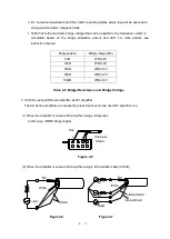
Figure 4-2 Bridge Box Connection
Summary of Contents for AS2503
Page 1: ...AS2503 AS2603 DC BRIDGE SYSTEM DYNAMIC STRAIN AMPLIFIERS INSTRUCTION MANUAL 1WMPD4003356 ...
Page 2: ......
Page 4: ......
Page 30: ......
Page 46: ......
Page 68: ......
Page 83: ...9 5 9 3 External Dimensions 9 3 1 Amplifier Unit AS2503 ...
Page 84: ...9 6 9 3 2 Amplifier Unit AS2603 ...
Page 85: ...9 7 9 3 3 Panel Cut Sizes ...
Page 87: ...9 9 9 3 5 Rack mount Case Rack Rail Elongate Hole ...

