4-9
e. Do not place transducers and their interconnecting cables where they will be exposed to
strong electric and/or magnetic fields.
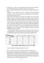
f. Table 5 lists the maximum bridge voltage that can be applied to the transducer, which is
calculated based on the bridge allowable current and drift. For more details, see
instruction manual.
Bridge resistor
Bridge voltage (B/V)
60Ω
Within 2V
120Ω
Within 3V
350Ω
Within 10V
500Ω
Within 12V
1000Ω
Within 12V
Table 4-5 Bridge Resistance and Bridge Voltage
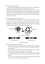
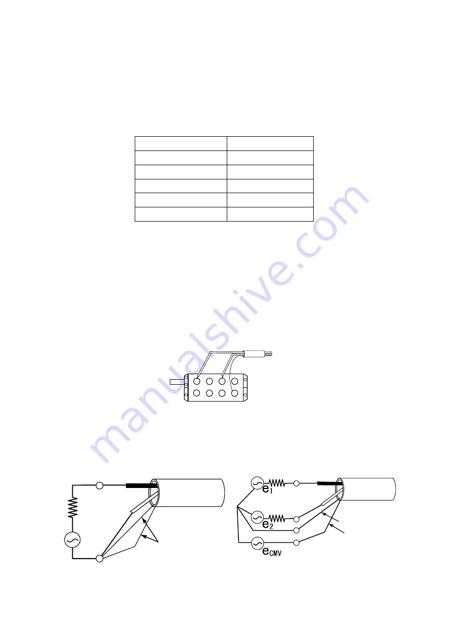
4.2.4 When using AS Series amplifier as DC amplifier
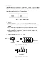
The AS Series amplifiers are measuring instrument but can be used DC amplifier, too.
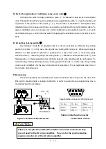
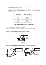
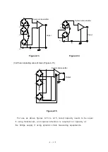
(1) When the amplifier is used as DC amplifier using a bridge box
In this case, CMRR drops slightly.
Figure 4-5
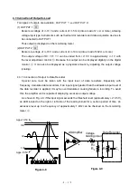
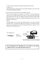
(2) When the amplifier is used as DC amplifier using a DC amplifier cable (47228)
A
E
B
C
D
Wire
Shield wire
Shield
+
-
Figure 4-6
Figure 4-7
White
Shield
Red
Signal
White
Internal shield
Internal shield
Red
Summary of Contents for AS2503
Page 1: ...AS2503 AS2603 DC BRIDGE SYSTEM DYNAMIC STRAIN AMPLIFIERS INSTRUCTION MANUAL 1WMPD4003356 ...
Page 2: ......
Page 4: ......
Page 30: ......
Page 46: ......
Page 68: ......
Page 83: ...9 5 9 3 External Dimensions 9 3 1 Amplifier Unit AS2503 ...
Page 84: ...9 6 9 3 2 Amplifier Unit AS2603 ...
Page 85: ...9 7 9 3 3 Panel Cut Sizes ...
Page 87: ...9 9 9 3 5 Rack mount Case Rack Rail Elongate Hole ...

