4-16
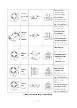
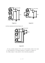
For details, refer to the remarks in the
“Wheatstone Bridge Connections Table”
on pages 4.4-4.5.
*Although transducers are generally based on the full-bridge configuration, their output is made
to match the quarter-bridge configuration.
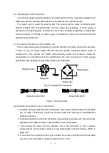
(3) Where the distance from the bridge box to the amplifier unit is long
If the cable from the bridge box or a transducer to the amplifier unit is long, the bridge supply
will drop due to the conductor resistance of the cable. This causes errors between the bridge
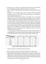
output voltage and the CAL value. For obtaining the voltage drop
rate, refer to “Bridge Voltage
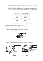
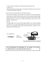
Drop Rate” on page 4.7 or measure the voltage drop rate between terminals A and C on the
bridge box, using a voltmeter.
Example:
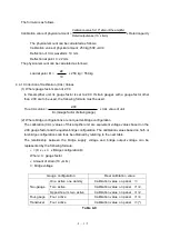
If the cable length is 100 m and the strain gauge resistance is 120
under an ambient
temperature of 20
C, the bridge supply voltage will be reduced by 5.8% between terminals A
and C, which can be obtained from the
“Bridge Voltage Drop Rate Table” on page 4.6. The true
calibration value can thus be given by:
True calibration value
= ×
Such measurement and adjustment are not needed in AS series
amplifiers thanks to wire length adjustment (Page 3-8).
1
1-0.058
A
E
B
C
D
Voltmeter
AC Voltage
Measurement
Bridge box
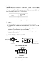
Figure.4-8 Voltage measurement on bridge box
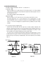
Calibration
value on display
Summary of Contents for AS2503
Page 1: ...AS2503 AS2603 DC BRIDGE SYSTEM DYNAMIC STRAIN AMPLIFIERS INSTRUCTION MANUAL 1WMPD4003356 ...
Page 2: ......
Page 4: ......
Page 30: ......
Page 46: ......
Page 68: ......
Page 83: ...9 5 9 3 External Dimensions 9 3 1 Amplifier Unit AS2503 ...
Page 84: ...9 6 9 3 2 Amplifier Unit AS2603 ...
Page 85: ...9 7 9 3 3 Panel Cut Sizes ...
Page 87: ...9 9 9 3 5 Rack mount Case Rack Rail Elongate Hole ...

