16
10. OPTIONS
The following options are available for the FG series:
?
OP-23 (FG-23)
RS-232C serial interface
?
OP-24 (FG-24)
RS-232C serial interface and Comparator relay output
?
OP-23 and OP-24 cannot be used together.
10-1. Installation of OP-23/OP-24
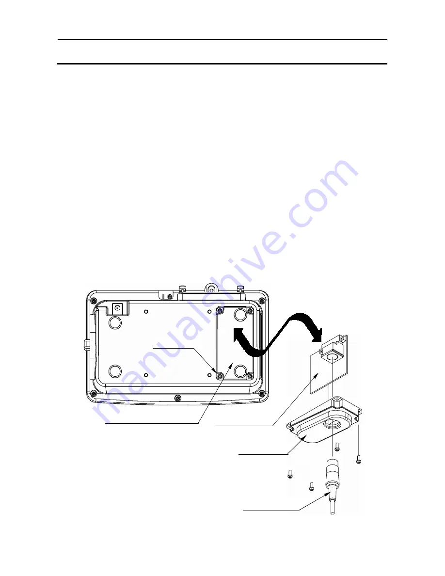
The OP-23/OP-24 has an interface board, an option panel and a DIN 8 pin connector.
The option panel and DIN connector are common to both options.
Before installation, prepare an interface cable using attached DIN connector. Or there
is a way to use the optional RS-232C cable (see “10-2. OP-23 RS-232C serial
interface”).
1. Disconnect the AC adapter from the scale.
2. Remove the four screws and the cover of option slot.
3. Thread the interface cable through the hole of option panel first, and connect the
DIN connector to the interface board.
4. Connect the interface board to the connector in the display pod.
5. Attach and fix the option panel using the screws that removed in the step 2.
`
Option slot for OP-23/24
(Cover)
Screws
Interface board
Option panel
Interface cable

