background image

- 15 - 


‰

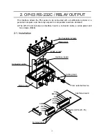
 Installation is similar to the OP-03. See “2-1. Installation”. 

‰

 Set the function parameters F04, F05, F06, F18, F19 and F20 according your 

application. 

‰

 The function setting F19-1 must be set for RS-422 and F19-2 must be RS-485. To 

connect more than one scale with a computer, set a different address to each scale 
by F18-##. 


3-2. OP-04 Specifications 

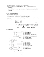
 RS-422/485 Specifications 

Transmission form 

Asynchronous, bi-directional, half-duplex 

Data format 

Baud rate:  2400, 4800, 9600 bps 


Data: 

7 bits + parity 1bit (even / odd) or 8 bits 

(non-parity) 
  

Start bit: 

1 bit 


Stop bit: 

1 bit 

  Code: 

ASCII 

  Terminator: 

C

R

L

F


LSB

0


1


2


3


4


5

MSB

6


Circuit diagram 


Solid sate relay


1  SDA (RS-422 Out) 
2  SDB (RS-422 Out) 
3  RDA (RS-422 In / RS-485 In-Out) 
4    RDB (RS-422 In / RS-485 In-Out) 
5  TRM (Termination) 
6  SG (Signal ground) 

1  Relay output HI 
2  Relay output LO 
3  Relay output OK 
4  Relay common COM 
5  Shield SHLD 
6  Frame ground FG 

FS-

i

inside

Stop bit 

   A-B 

1 (-2V~-5V) 

0 (2V~15V) 

Start bit

Data bit

Parity bit

Summary of Contents for FS-03i

Page 1: ...WM PD4001368 F FS S i i S Se er ri ie es s C Ch he ec ck k W We ei ig gh hi in ng g S Sc ca al le es s O Op pt ti io on n OP 02 OP 03 OP 04...

Page 2: ...stitute Product Safety Signs and Labels The meanings are as follows WARNING A potentially hazardous situation which if not avoided could result in death or serious injury CAUTION A potentially hazardo...

Page 3: ...Comparator light ON approximately 25 hours The battery will take about 15 hours to be fully charged The battery life will vary depending on how the scale is used the ambient temperature and so on Ins...

Page 4: ...power cord again and check that the scale still works Charging the battery When the weight display shows lb1 the battery voltage is low in voltage and should be recharged Connect the main power cord...

Page 5: ...utputs for comparator result are obtained The OP 03 unit includes an interface board a connector cable a cable gland and two screws M3x6 2 1 Installation Ten hexagon screws Rear cover Connector cable...

Page 6: ...cluded in the OP 03 6 Tighten the cable gland and attach the rear cover to the front display firmly using the ten hexagon bolts 7 Connect the main power cord to the outlet 8 Set the function parameter...

Page 7: ...ts _ k g Weighing unit kg _ _ g Weighing unit g _ l b Weighing unit lb _ o z Weighing unit oz _ _ HI LO limit F07 2 Example of data Weighing data kg S T 0 0 1 2 3 4 5 _ k g CR LF Weighing data g S T 0...

Page 8: ...ccur until after the weight display falls below 5d Auto print Mode data F06 4 Data is sent if the weight display is stable at 5d d weighing display division and above below The next transmission can n...

Page 9: ...mory number Examples of command and reply _ shows Space 20H Examples below are for F20 0 Reply to command is sent Request a weight data Command Q C LF Reply S T 0 0 1 2 3 4 5 _ k g C LF Stable Positiv...

Page 10: ...LF Send a target weight in use Command O K C LF Reply O K 0 0 0 1 0 0 0 _ k g C LF Send a HI limit value or upper limit weight in use Command H I C LF Reply H I 0 0 0 3 0 5 0 _ k g C LF Upper limit w...

Page 11: ...0 C LF Decimal point follows the weight display Reply L O 0 0 0 1 0 0 C LF FS 15Ki F07 0 0 100 kg will be set as a lower limit weight F07 1 0 100 kg will be set as a LO limit weight F07 2 is set the c...

Page 12: ...ed memory number No reply for F20 1 Command C M 0 1 C LF Clear the contents of memory number 01 Reply C M 0 1 C LF Reply in case of the function setting F20 0 There are other replies to the commands o...

Page 13: ...ta Code WT Weight CM Comma 2CH TR Tare weight in use SP Space 20H CP Comparator result CR CR 0DH OK Target weight LF LF 0AH HI HI limit value or upper limit weight LO LO limit value or lower limit wei...

Page 14: ...ata 3 digit unit TR _ _ _ 1 2 3 4 _ k g 1 234 kg 9 digit tare data 3 digit unit CP O K Comparator result OK 2 characters H I Comparator result HI 2 characters L O Comparator result LO 2 characters _ _...

Page 15: ...s an interface board a connector cable two cable glands and two screws M3x6 The relay output specifications are same as the OP 03 See 2 2 OP 03 Specifications 3 1 Installation Ten hexagon screws Rear...

Page 16: ...mission form Asynchronous bi directional half duplex Data format Baud rate 2400 4800 9600 bps Data 7 bits parity 1bit even odd or 8 bits non parity Start bit 1 bit Stop bit 1 bit Code ASCII Terminator...

Page 17: ...f the scale to send a command at the head of command of the RS 232C All of data or reply from the scale have at the head Connect TRM with RDB at the farthest FS i from the host computer Host computer...

Page 18: ...nd 2 3 Q C LF Reply 2 3 S T 0 0 1 2 3 4 5 _ k g C LF Stable data 2 3 U S 0 0 0 7 8 9 0 _ k g C LF Unstable data 2 3 O L 9 9 9 9 9 9 9 _ k g C LF E display Zero the scale No reply for F20 1 Command 2 3...

Reviews: