Page 8
HV/HW-C/CP Series
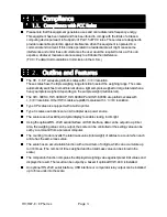
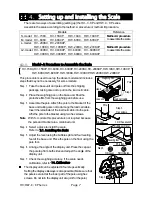
4.1.2. Method-B Procedure to Assemble the Scale
HV
-
300KC, HV
-
300KCP, HV
-
600KC, HV
-
600KCP,
HW
-
300KC, HW
-
300KCP, HW
-
600KC, HW
-
600KCP
This procedure is used to set up the above models.
Note
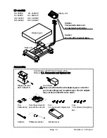
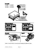
Display unit, pole and base unit are connected by
cable. Take care not to pull on the load cell cable.
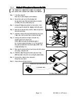
Step 1 Take the display unit, base unit and pole out
from the shipping package taking care not to pull
on the load cell cable.
Step 2 Remove the weighing pan.
Step 3 Assemble the pole and display unit.
Affix the pole and display unit using four
4
mm
screws. Use the Phillips screwdriver included.
Bundle the AC adapter cable and
communication cable using two cable clamps
that affix to the pole.
Step 4 Arrange the angle of the display unit.
Press the caps at the pole top from both sides
and adjust the angle of the display unit.
Step 5 Connecting the load cell cable.
Connect the load cell cable to the display unit.
Close the cable cover, hook the cable in hooks
and adjust cable length. Close the bracket cover.
Step 6 Assemble the base unit and pole.
Affix the pole and base unit using four hex
screws (and flat washers) so as not to damage
the load cell cable. Use the hex wrench included.
Bundle the remainder of the load cell cable using
the included cable ties.
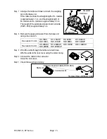
Step 7 Place the weighing pan on the base unit.
Affix the weighing pan using four
5
mm screws.
Use the Phillips screwdriver included. Peel the
protective film from the weighing pan.
Step 8 Select a place for installing the scale.
Refer to "
3.1. Installing the Scale
" .
Step 9 Adjust the bubble spirit level.
Adjust the level of the base unit using the bubble
spirit level and the leveling feet.
Step 10 Check the weighing accuracy. If the scale
needs calibration, refer to "
14. Calibration
".
Four hex screws
Hex wrench
to affix pole
Step
6
Four flat washer
Tied cable
Pole
Weighing pan
OK:
Level
NO:
Inclination
Bubble spirit level
Four
5
mm screws
Leveling foot
Step 9
Step 7
Step 5
Cable cover
Connector
Load cell cable
Step
4
Bracket cover
Hook
Accessory
Step 2
Weighing Pan
box
Display unit
box
Tied cable
Base unit
Cable cover
Load cell cable
Pole
Display
unit Step
3
Four
4
mm screws
Phillips screwdriver
Pole
Cable clamp
(
2
pieces)
Summary of Contents for HV-C Series
Page 89: ...HV HW C CP Series Page 87 MEMO...
Page 90: ...Page 88 HV HW C CP Series MEMO...
Page 91: ...13...


