May 2014 – TD 293 OPERATING MANUAL – SmartGuard
Page 37
6.1
Accessing the Device layout
Select the AADI Real-Time Collector SmartGuard connection, and press
Open Port
to open the connection.
Open
Control Panel < Recorder Panel
and stop recording.
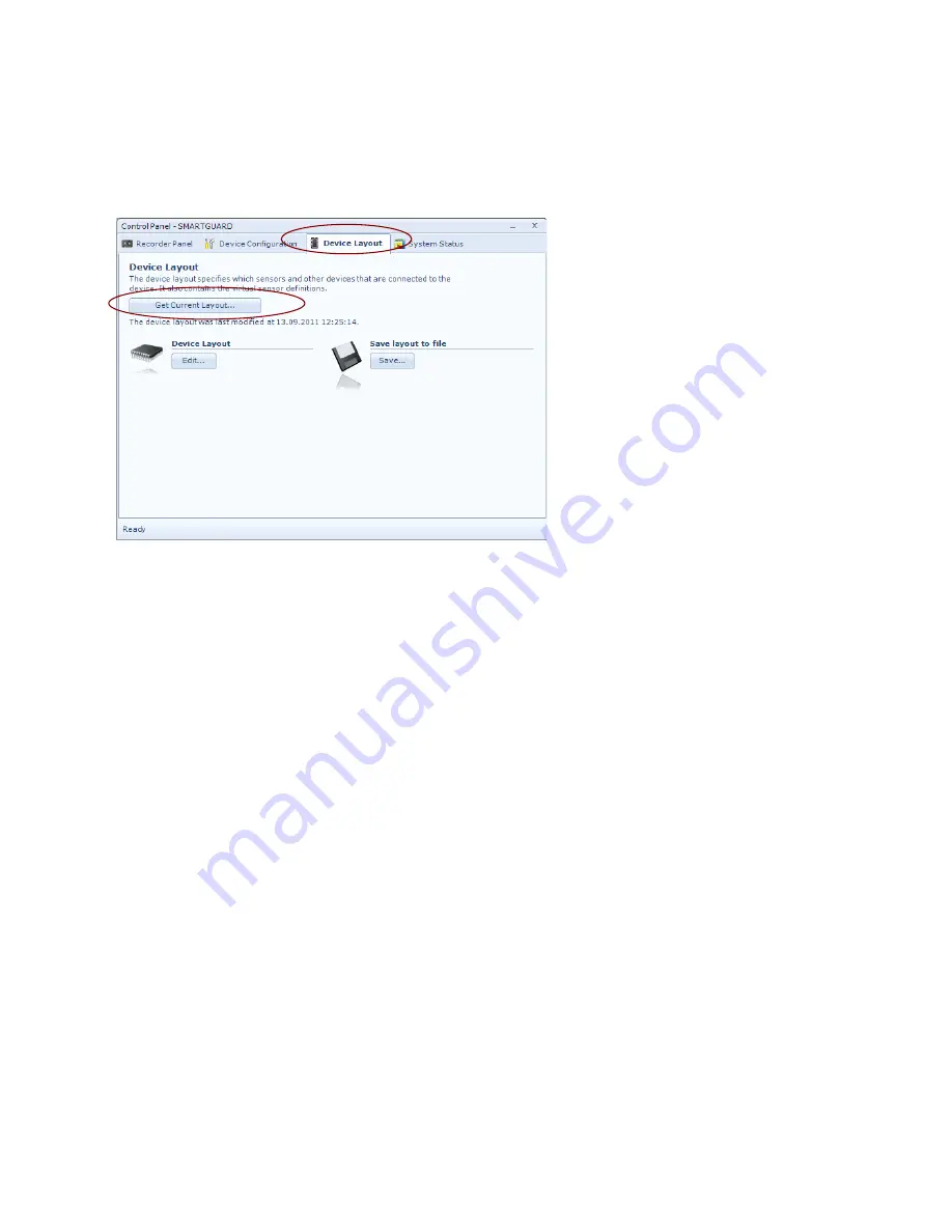
Select the
Device Layout
tab, and
press
Get Current Layout...
to view
the current device layout on the PC.
Note! The password is: 1000
Select
Save layout to file
and press
Save…
to save current layout to file.
Select
Device Layout
and press
Edit…
to add new sensors/modem or edit
existing layout. Refer chapters 6.2 to
6.5 for a description of layout for
different type of sensors and
modem:
•
Serial sensor
•
SR10/VR22 sensor
•
Analog sensor
•
Digital sensor
•
Communication
•
Routing
6.2
Serial sensors
When adding a new serial sensor, you must carefully consider the sensor data format:
•
If the data formats list already contains a file format that fits the actual sensor data stream, then you can
select that data format. Refer chapter 6.2.2 to continue when the data format is defined.
•
If not, you must define a new format to fit the data stream from the sensor. Refer chapter 6.2.1 for
defining a data format that fits the actual sensor.
Figure 6-1 Device Layout panel.


