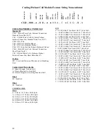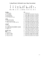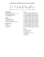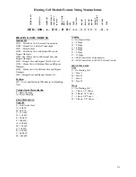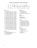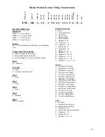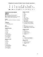
Heating Coil Module Feature String Nomenclature
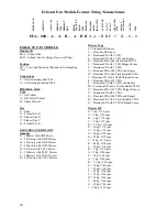
M
O
DULE
ID
PO
SIT
IO
N
AIRFL
O
W
EL
EC H
EAT
CAPA
CIT
Y
STA
G
IN
G
H
EAT
C
O
IL
SIZ
E
RO
WS
FPI
TYPE
CO
ATI
N
G
BL
ANK
B
L
AN
K
BL
ANK
BL
ANK
MOD
UL
E
AC
CE
S
S
OR
Y
ACCESS
TYPE
HCD -
000 - A - H E - B B
C A A - 0 0 0 0 0 - B - 0
22
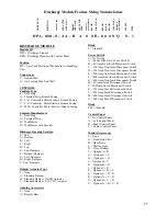
FPI
0 = No Heating Coil
A = 8 FPI, 0.0060” Fin Thick, 0.017” Tube Wall
B = 10 FPI, 0.0060” Fin Thick, 0.017” Tube Wall
C = 12 FPI, 0.0060” Fin Thick, 0.017” Tube Wall
D = 8 FPI, 0.0075” Fin Thick, 0.017” Tube Wall
E = 10 FPI, 0.0075” Fin Thick, 0.017” Tube Wall
F = 12 FPI, 0.0075” Fin Thick, 0.017” Tube Wall
G = 8 FPI, 0.0100” Fin Thick, 0.017” Tube Wall
H = 10 FPI, 0.0100” Fin Thick, 0.017” Tube Wall
J = 12 FPI, 0.0100” Fin Thick, 0.017” Tube Wall
K = 8 FPI, 0.0060” Fin Thick, 0.025” Tube Wall
L = 10 FPI, 0.0060” Fin Thick, 0.025” Tube Wall
M = 12 FPI, 0.0060” Fin Thick, 0.025” Tube Wall
N = 8 FPI, 0.0075” Fin Thick, 0.025” Tube Wall
P = 10 FPI, 0.0075” Fin Thick, 0.025” Tube Wall
Q = 12 FPI, 0.0075” Fin Thick, 0.025” Tube Wall
R = 8 FPI, 0.0100” Fin Thick, 0.025” Tube Wall
S = 10 FPI, 0.0100” Fin Thick, 0.025” Tube Wall
T = 12 FPI, 0.0100” Fin Thick, 0.025” Tube Wall
U = 8 FPI, 0.0060” Fin Thick, 0.035” Tube Wall
V = 10 FPI, 0.0060” Fin Thick, 0.035” Tube Wall
W = 12 FPI, 0.0060” Fin Thick, 0.035” Tube Wall
Y = 8 FPI, 0.0075” Fin Thick, 0.035” Tube Wall
Z = 10 FPI, 0.0075” Fin Thick, 0.035” Tube Wall
1 = 12 FPI, 0.0075” Fin Thick, 0.035” Tube Wall
2 = 8 FPI, 0.0100” Fin Thick, 0.035” Tube Wall
3 = 10 FPI, 0.0100” Fin Thick, 0.035” Tube Wall
4 = 12 FPI, 0.0100” Fin Thick, 0.035” Tube Wall
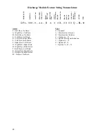
Type
0 = No Heating Coil
A = Hot Water, Full Serpentine (2 Rows Only)
B = Hot Water, Half Serpentine
C = Hot Water, Quarter Serpentine
D = Steam Distributing
Coating
0 = No Heating Coil
A = Galvanized Coil Casing
B = Polymer E-Coated Coil
C = Stainless Steel Coil Casing
D = Stainless Steel Coil Casing, Copper Fins
Blank
0000 = Standard
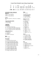
Module Accessories
0 = None
A = Heating Coil Drain Pan
Access
0 = No Drain, Left Coil Connections
A = No Drain, Right Coil Connections
B = Left Drain, Left Coil Connections
C = Left Drain, Right Coil Connections
D = Right Drain, Left Coil Connections
E = Right Drain, Right Coil Connections
F = Both Drain, Left Coil Connections
G = Both Drain, Right Coil Connections
H = No Drain, No Coil Connections
Type
0 = Standard
A = Stainless Steel Interior
B = Stainless Steel Exterior
C = Options A + B
X = Special Pricing Authorization
Y = Options A + X
Z = Options B + X
1 = Options A + B + X
Summary of Contents for M3 Series
Page 53: ...53 Figure 28 Example Blow Through AAONEcat32 Rating Sheet ...
Page 73: ...73 ...
Page 74: ...74 ...
Page 75: ...75 ...

