45
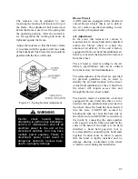
The isolators can be adjusted by first
loosening the locking bolt located on top of
the frame. The adjustment bolt located just
below the frame is used to set the spring into
the operating position. After the isolator is
set for operation the locking bolt must be
tightened against the frame.
Adjust the isolators so that the blower frame
is in contact with the gasket on all four sides
of the bulkhead. The blower frame should be
parallel with the base of the unit.
Figure 21 - Spring Isolator Adjustment
Blower Wheels
AAON units are equipped with a backward
curved blower wheels that is set to deliver
the air volume specified according to unit
size and/or job requirements.
Air Adjustment
In the event that reduced air volume is
required, an air volume band can be installed
within the blower wheel to reduce the
amount of air delivery. If the unit is factory
equipped with the air band but additional air
delivery is needed, the band can be removed
from the wheel.
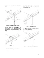
The air band is sized according to the air
delivery specifications and can be ordered
from the factory for field installation.
The related photos of the wheel are provided
for practical guidelines only in order to
identify the air band location in the wheel.
Actual field installation of the air band into
the wheel will require access into and
through the blower wheel venturi.
The band is made of aluminum, sized and
equipped with easy bend tabs that are to be
inserted into pre-punched slots provided on
the wheel. Once the band has been inserted
into the slots, it MUST BE secured by
bending the tabs over from the back side of
the wheel and also MUST BE secured from
the inside by connecting the ends together
with a pop-rivet in the holes provided on the
ends of the band. If the band is to be field
installed, a hand held pop-rivet tool is
recommended for connecting the band ends
together. Caution must be taken to assure
that the band is tightly installed and no
damage, denting, or alteration to the wheel
or blades occurs during the installation.
Electric
shock
hazard.
Before
attempting to perform any installation,
service, or maintenance, shut off all
electrical power to the unit at the
disconnect switches. Unit may have
multiple power supplies. Failure to
disconnect power could result in
dangerous operation, serious injury,
death, or property damage.
WARNING
Summary of Contents for M3 Series
Page 53: ...53 Figure 28 Example Blow Through AAONEcat32 Rating Sheet ...
Page 73: ...73 ...
Page 74: ...74 ...
Page 75: ...75 ...


