48
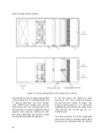
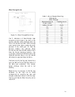
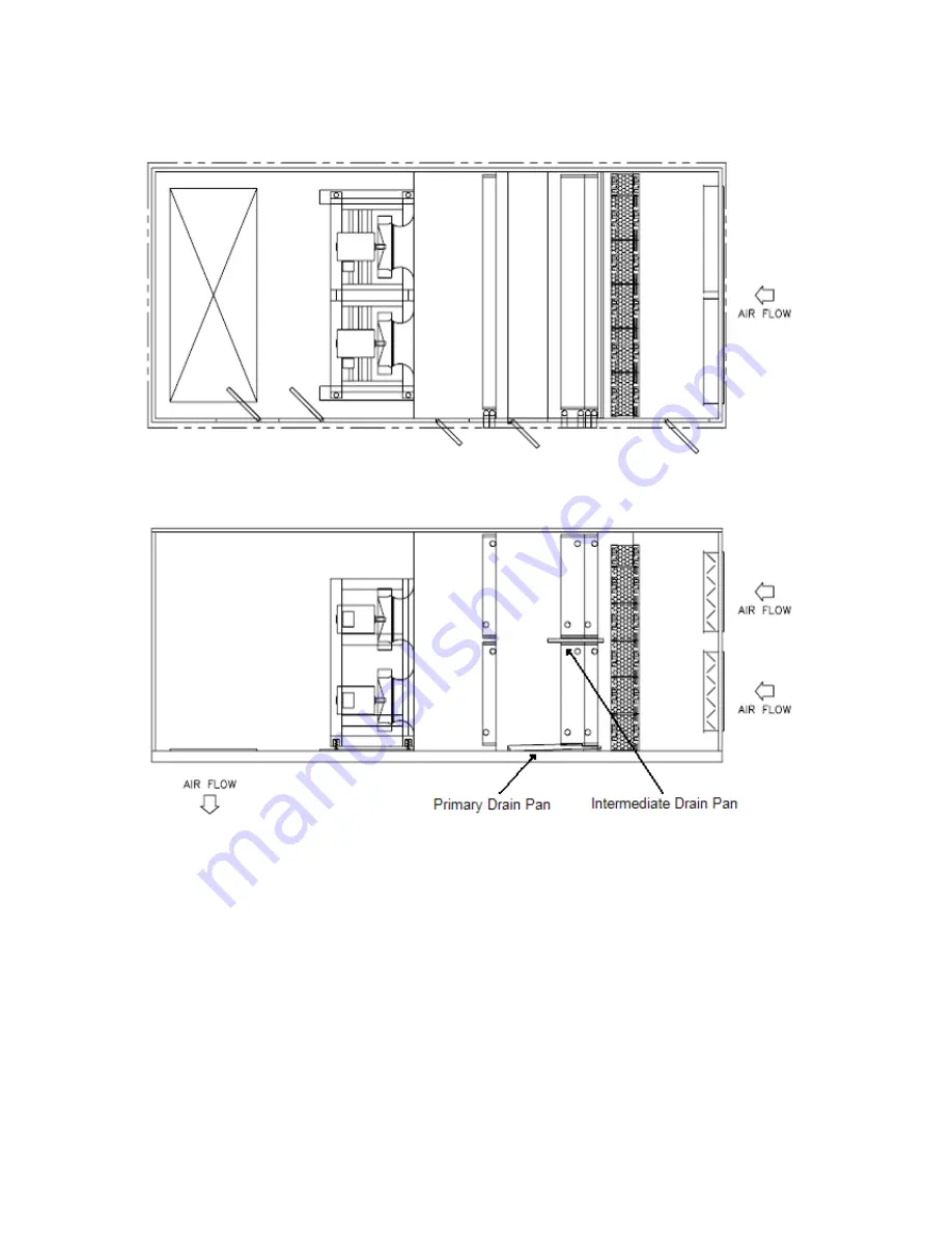
Draw-Through P-Trap Example
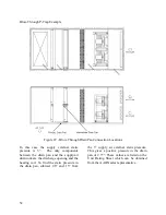
Figure 24 – Draw-Through Drain Pan Connection Locations
The unit shown above is a draw-through unit
with a mixing box, 12” cartridge filters with
2” pleated pre-filters, hot water preheat
coils, chilled water cooling coils, and hot
water reheat coils. The static pressure in the
drain pan area is found by finding the largest
negative static pressure entering the unit,
and then subtracting any pressure drops
between that point and the drain pan.
In the case below the outside air static
pressure is -0.75” due to duct loss between
the unit and the outside air intake. The
return air static pressure is -1.5” due to the
building pressure and duct loss between the
space and the unit. In this case the -1.5”
would be used.
The static pressures of all the components
between the return air opening and the drain
pan need to be subtracted from the external
Summary of Contents for M3 Series
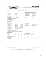
Page 53: ...53 Figure 28 Example Blow Through AAONEcat32 Rating Sheet ...
Page 73: ...73 ...
Page 74: ...74 ...
Page 75: ...75 ...

