COMMUNICATING WIRING
MODGAS-XWR-1 Technical Guide
14
2V2IGN2S - Communicating Wiring
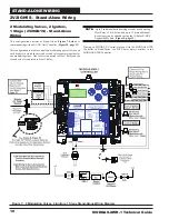
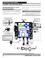
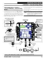
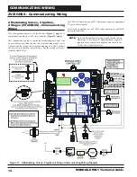
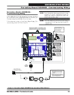
Figure 11: 2 Modulating Valves, 2 Ignitors, 2 Stage Communicating Wiring Diagram
2 Modulating Valves, 2 Ignitors,
2 Stages (2V2IGN2S) - Communicating
Wiring
This confi guration operates as Stand-Alone (
Figure 3, page 6
) or
communicating with an AAON Unit Controller (
Figure 11, below
).
This confi guration is used to control two modulating gas valves (one
on each header), in which the fi rst valve is modulating stage 1 (valve
1 header) and the second valve is modulating stage 2 (valve 2 header).
The fi rst valve is attached to Heat Relay 1 and the second valve is at-
tached to Heat Relay 2.
For VCM-X Controllers, use an I
2
C Cable connecting to the appropriate
I
2
C port on the controller.
For all other controllers, use an E-BUS cable connecting to an E-BUS
port on the controller.
NOTE:
Up to 2 additional fi xed heat stages can be used by using
Heat Relays 3 & 4 below. If additional fi xed stages are
required, these should be confi gured and wired to the
AAON Unit Controller’s relays.

