TABLE OF CONTENTS
OVERVIEW & FEATURES .................................................................................................. 3
INSTALLATION & WIRING ................................................................................................. 4
Important Wiring Considerations & Module Dimensions .......................................................................................... 4
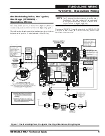
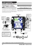
1V1IGN1S 1 Valve, 1 Ignitor, 1 Stage Stand Alone Wiring ...................................................................................... 5
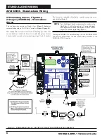
2V2IGN2S 2 Valves, 2 Ignitors, 2 Stages Stand Alone Wiring & Secondary Board Wiring ..................................... 6
2V1IGN1S 2 Valves, 1 Ignitor, 1 Stage Stand Alone Wiring & Secondary Board Wiring ......................................... 8
2V2IGN1S 2 Valves, 2 Ignitors, 1 Stage Stand Alone Wiring ................................................................................ 10
12 E-BUS Expansion Board Wiring ....................................................................................................................... 11
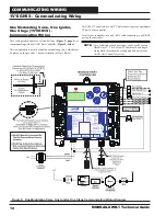
1V1IGN1S 1 Valve, 1 Ignitor, 1 Stage Communicating Wiring ............................................................................... 12
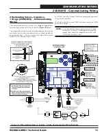
2V2IGN1S 2 Valves, 2 Ignitors, 1 Stage Communicating Wiring ........................................................................... 13
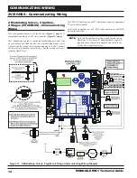
2V2IGN2S 2 Valves, 2 Ignitors, 2 Stages Communicating Wiring & Secondary Board Wiring .............................. 14
2V1IGN1S 2 Valves, 1 Ignitor, 1 Stage Communicating Wiring & Secondary Board Wiring ................................. 16
INPUTS/OUTPUTS ........................................................................................................... 18
OPERATION MODES & STAGING CONFIGURATIONS ..................................................... 19
SEQUENCE OF OPERATIONS .......................................................................................... 20
LCD DISPLAY SCREENS .................................................................................................. 22
TROUBLESHOOTING ....................................................................................................... 29
APPENDIX A - Supply Air Temperature Sensor Guide ................................................... 34
APPENDIX B - MODGAS-XWR-1 Replacement of MODGAS-XWR ................................... 36
PART DESCRIPTION
PART NUMBER
MODGAS-XWR-1 Controller
V82790
MODGAS-XWR Controller
V20780
VCCX2 Controller
V87900
VCB-X Controller
V28940
VCM-X Modular E-BUS Controller
V07150
12-Relay E-BUS Expansion Module
R69180
Supply Air Temperature Sensor
P87140
AAON, Inc.
2425 South Yukon Ave.
Tulsa, OK 74107-2728
www.aaon.com
Factory Technical Support Phone: 918-382-6450
Controls Support Phone: 866-918-1100
This document is subject to change without notice.
AAON Part Number: V73440, Rev. 01B
All rights reserved. © November 2018 AAON, Inc.
AAON
®
assumes no responsibility for errors or omissions in
this document.
AAON
®
is a registered trademark of AAON, Inc., Tulsa, OK.
White-Rogers
®
is a registered trademark of Emerson Climate
Technologies, Inc., St. Louis, MO
www.aaon.com
This manual is also available for download from our
website—aaon.com—where you can always
fi
nd the
latest literature updates.

