MODGAS-XWR-1 Technical Guide
TROUBLESHOOTING
29
LED Diagnostics
LED Diagnostics
The MODGAS-XWR Controller is equipped with LEDs that can be
used to verify operation and perform troubleshooting. There are LEDs
for communication, operation modes, and diagnostic codes. The module
has 14 LEDs—12 used for operation & status, and 2 used for alarms.
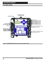
See
Figure 16, page 30
for the LED locations. The LEDs associated
with these inputs and outputs allow you to see what is active without
using a voltmeter. The LEDs and their uses are as follows:
Operation LEDs
POWER
- This green LED will light up to indicate that 24 VAC power
has been applied to the controller.
STATUS
- This green LED will blink every 5 seconds according to
what mode the controller is in. See
Table 3
.
No. of
Blinks
STATUS LED
1
Off Mode
2
Heating Mode (Heat Enable
Signal and No Alarms)
Table 3: STATUS LED Blink Codes
Diagnostic LEDs
ALARM
- The red LED located on the MODGAS-XWR Controller’s
cover above the LCD display will blink to indicate an alarm. Alarms can
be viewed on the LCD Display in the ALARMS Menu.
The ALARM LED located above the COMM LED on the MODGAS-
XWR board will blink an alarm code every 10 seconds when an alarm(s)
occurs. The highest priority failure code will be indicated fi rst. You
must correct the highest priority alarm before other problems will be
indicated. See
Table 4
.
No. of
Blinks
ALARM LED
(Blinks every 10 seconds)
1
Valve 1 Proof of Flame Failure
2
Valve 1 Not Detected
3
Valve 2 Proof of Flame Failure
4
Valve 2 Not Detected
5
SAT Not Detected (Stand-Alone Mode)
6
SAT Cutoff
7
Relay 12 Communication Failure
8
Communication Failure
9
Stage 1 Failure
10
Stage 2 Failure
Table 4: ALARM LED Blink Codes
Communication LED
COMM
- This yellow LED will light up and blink when communications
are detected. If this LED never blinks, then there is no communication.
Relay LEDs
RLY1
- This green LED will light up and stay lit as long as the Fan
relay is active.
RLY2
- This green LED will light up and stay lit as long as the Low
Speed Fan relay is active.
RLY3
- This green LED will light up and stay lit as long as the Heat
Enable 1 relay is active.
RLY4
- This green LED will light up and stay lit as long as the Heat
Enable 2 relay is active.
RLY5
- This green LED will light up and stay lit as long as the Heat
Enable 3 relay is active.
RLY6
- This green LED will light up and stay lit as long as the Heat
Enable 4 relay is active.
Binary Input LEDs
AUX BIN
- Not used.
HEAT EN
- This green LED will light up when Heat Enable signal is
activated.
PO-IGN1
- This green LED will light up when the Proof of Flame input
from the fi rst Ignition Module is enabled.
PO-IGN2
- This green LED will light up when the Proof of Flame input
from the second Ignition Module is enabled.
Analog Output LEDs
GAS VALVE 1
- This red LED will do the following:
•
If the valve is detected and not modulating, then the
valve LED is solid.
•
If the valve is modulating, then it will blink while it is
moving.
•
If the valve is not detected, the valve LED will
continuously blink.
•
If there shouldn’t be a modulating valve attached to the
valve header, then the valve LED remains off .
GAS VALVE 2
- This red LED will do the following:
•
If the valve is detected and not modulating, then the
valve LED is solid.
•
If the valve is modulating, then it will blink while it is
moving.
•
If the valve is not detected, the valve LED will
continuously blink.
•
If there shouldn’t be a modulating valve attached to the
valve header, then the valve LED remains off .

