67
tower/geothermal loop and self-contained
unit. System must be sized in accordance
with the ASHRAE Handbook. Use
engineering guidelines to maintain equal
distances for supply and return piping and
limit bend radii to maintain balance in the
system. Balancing valves, permanent
thermometers and gauges may be required.
Before connection to the unit the condenser
water system must be flushed to remove
foreign material that could cause condenser
fouling. Install a screen strainer with a
minimum of 20 Mesh ahead of the condenser
inlet to prevent condenser fouling and
internal tube damage.
Mineral content of the condenser water must
be controlled. All make-up water has
minerals in it and as the water is evaporated
in the cooling tower, these minerals remain.
As the mineral content of the water increases,
the conductivity of the water increases.
Field provided and installed water treatment
program must be compatible with stainless
steel, copper, aluminum, ABS plastic, and
PVC. Batch feed processes must never be
used as concentrated chemicals can cause
corrosion. Never use hydrochloric acid
(muriatic acid) or chlorine as it will corrode
stainless steel.
NOTE:
Ball valves must be installed in the
condenser water supply and return lines for
unit isolation and water flow balancing. All
manual flow valves must be of the ball valve
design. Globe or gate valves must not be used
due to high pressure drops and poor throttling
characteristics.
Pressure and temperature ports are
recommended in condenser water supply and
return lines for system balancing. These
openings must be 5 to 10 pipe diameters from
the unit water connections. To allow for
mixing and temperature stabilization, wells
in the water piping must extend at least 1/2
pipe diameter into the pipe.
WATER PIPING
Follow national and local codes when
installing water piping. Connections to
the unit must incorporate vibration
eliminators to reduce noise and
vibration and shutoff valves to
facilitate servicing. Supply and return
water piping must be at least as large
as the unit connections and larger
depending on length of runs, rise and
bends.
CAUTION
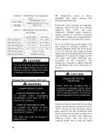
Each heat exchanger is equipped with
a refrigerant pressure relief device to
relieve pressure should excessive
condensing pressures (>4.65 kpa
[675 psig]) occur. Codes may require
a qualified technician to connect and
route relief piping outdoors. The relief
valve has a 16mm (5/8”) male flare
outlet connection.
CAUTION
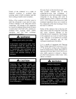
A qualified technician is responsible
for properly sizing and installing water
system components. Improper fluid
flow due to valves, piping, or improper
pump operation may result in
unacceptable unit operation and void
warranty.
CAUTION
Summary of Contents for RQ NextGen Series
Page 2: ......
Page 26: ...26 Figure 3 RQ Cabinet Standard and Power Exhaust Gasket Locations...
Page 40: ...40 Figure 23 Post Corner Hole Piping Figure 24 Post Back Hole Piping...
Page 88: ...88 Gas Heater Operating Instructions Figure 36 Gas Heater Instructions...
Page 95: ...95...
Page 96: ...96...
Page 105: ...105 Maintenance Log E Coated Coil...
Page 107: ...107...

