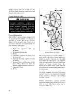
69
Wiring diagrams are provided with each
motor. When wired according to wiring
diagram, energy recovery wheel rotates
clockwise when viewed from the shaft/pulley
side.
By carefully reviewing the information
within this section and following the
instructions, the risk of improper operation
and/or component damage will be
minimized.
It is important that periodic maintenance be
performed to help assure trouble free
operation.
Initial Mechanical Check and Setup
Outdoor units equipped with outside air
intake will have an outside air hood. The
outside air hood must be opened prior to unit
operation.
Outdoor air intake adjustments must be made
according to building ventilation, or local
code requirements.
After the unit installation is complete, open
the cassette access door and determine that
the energy wheel rotates freely when turned
by hand with no interference noise. Apply
power and observe that the wheel rotates at
approximately 45-50 RPM. If the wheel does
not rotate when power is applied, it may be
necessary to readjust the “diameter air seals”.
Air Seal Adjustments
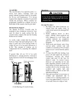
Pile type air seals across both sides of the
energy wheel diameter are factory adjusted to
provide close clearance between the air seal
and wheel.
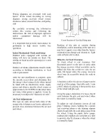
Cross Section of Air Seal Structure
Racking of the unit or cassette during
installation, and/or mounting of the unit on a
non-level support or in other than the factory
orientation can change seal clearances. Tight
seals will prevent rotation.
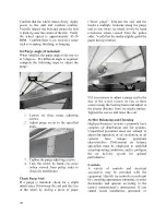
Wheel to Air Seal Clearance
To check wheel to seal clearance; first
disconnect power to the unit, in some units
the energy recovery wheel assembly can be
pulled out from the cabinet to view the air
seals. On larger units, the energy recovery
wheel may be accessible inside the walk-in
cabinet.
A business card or two pieces of paper can be
used as a feller gauge, (typically each .1 mm
[.004”] thick) by placing it between the face
of the wheel and pile seal.
Using the paper, determine if a loose slip fit
exist between the pile seal and wheel when
the wheel is rotated by hand.
To adjust air seal clearance, loosen all seal
plate retaining screws holding the separate
seal retaining plates to the bearing support
channels and slide the seals plates away from
the wheel. Using the paper feeler gauge,
readjust and retighten one seal plate at a time
to provide slip fit clearance when the wheel
is rotated by hand.
Summary of Contents for RQ NextGen Series
Page 2: ......
Page 26: ...26 Figure 3 RQ Cabinet Standard and Power Exhaust Gasket Locations...
Page 40: ...40 Figure 23 Post Corner Hole Piping Figure 24 Post Back Hole Piping...
Page 88: ...88 Gas Heater Operating Instructions Figure 36 Gas Heater Instructions...
Page 95: ...95...
Page 96: ...96...
Page 105: ...105 Maintenance Log E Coated Coil...
Page 107: ...107...


