44
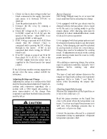
Subtract the measured liquid line temperature
from the saturated temperature to determine
the liquid sub-cooling.
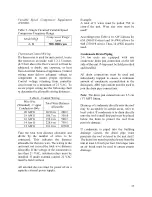
Compare calculated sub-cooling to Table 7
and Table 8 for the appropriate unit type and
options.
Checking Evaporator Superheat
Measure the temperature of the suction line
close to the compressor. Read gauge pressure
at the suction line close to the compressor.
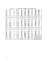
Convert the pressure obtained to a saturated
temperature using the appropriate refrigerant
temperature-pressure chart.
Subtract the saturated temperature from the
measured suction line temperature to
determine the evaporator superheat.
Compare calculated superheat to the table
below for the appropriate unit type and
options.
Table 9 - Acceptable Refrigeration Circuit
Values (Metric)
Air-Cooled Cond./Air-Source Heat Pump
In Cooling Mode
Sub-Cooling
4.4-8.3°C / 1.1-2.2°C
(HP)*
Sub-Cooling with
Hot Gas Reheat
4.4-8.3°C /1.1-3.3°C
(HP)*
Superheat
4.4-8.3°C
Water-Cooled Cond./Water-Source Heat
Pump In Cooling Mode
Sub-Cooling
2.2-4.4°C
Superheat
4.4-8.3°C
Table 10 – Acceptable Refrigeration Circuit
Values (Imperial)
Air-Cooled Cond./Air-Source Heat
Pump In Cooling Mode
Sub-Cooling
8-15°F / 2-4°F
(HP)*
Sub-Cooling with
Hot Gas Reheat
8-15°F /2-6°F
(HP)*
Superheat
8-15°F
Water-Cooled Cond./Water-Source
Heat Pump In Cooling Mode
Sub-Cooling
4-8°F
Superheat
8-15°F
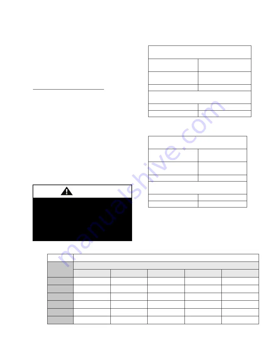
Table 11 - Acceptable Microchannel Air-Cooled Condenser Coil Liquid Sub-
Cooling Values (Metric)
Cooling Mode Liquid Sub-Cooling Values(°C)
Ambient
(°C)
Evaporator Coil Saturation Temperature (°C)
4.4
7.2
8.9
10.0
12.8
19.4
5.0 - 7.8
4.4 - 7.2
4.4 - 7.2
3.9 - 6.7
2.8 - 5.6
22.2
5.6 - 8.3
5.0 - 7.8
5.0 - 7.8
4.4 - 7.2
3.9 - 6.7
27.8
5.6 - 8.3
5.6 - 8.3
5.6 - 8.3
5.0 - 7.8
3.9 - 6.7
35.0
5.6 - 8.3
5.6 - 8.3
5.6 - 8.3
5.0 - 7.8
4.4 - 7.2
40.6
6.1 - 8.9
6.1 - 8.9
5.6 - 8.3
5.6 - 8.3
4.4 - 7.2
46.1
5.6 - 8.3
6.1 - 8.9
6.1 - 8.9
6.1 - 8.9
5.0 - 7.8
Thermal expansion valve must be
adjusted to approximately 4.4-8.3°C
(8-15°F) of suction superheat. Failure
to have sufficient superheat will
damage the compressor and void the
warranty.
CAUTION
Summary of Contents for RQ NextGen Series
Page 2: ......
Page 26: ...26 Figure 3 RQ Cabinet Standard and Power Exhaust Gasket Locations...
Page 40: ...40 Figure 23 Post Corner Hole Piping Figure 24 Post Back Hole Piping...
Page 88: ...88 Gas Heater Operating Instructions Figure 36 Gas Heater Instructions...
Page 95: ...95...
Page 96: ...96...
Page 105: ...105 Maintenance Log E Coated Coil...
Page 107: ...107...

