76
pulled out from the cabinet to view the air
seals. On larger units, the energy recovery
wheel may be accessible inside the walk-in
cabinet.
A business card or two pieces of paper can be
used as a feller gauge, (typically each .004”
thick) by placing it between the face of the
wheel and pile seal.
Using the paper, determine if a loose slip fit
exist between the pile seal and wheel when
the wheel is rotated by hand.
To adjust air seal clearance, loosen all seal
plate retaining screws holding the separate
seal retaining plates to the bearing support
channels and slide the seals plates away from
the wheel. Using the paper feeler gauge,
readjust and retighten one seal plate at a time
to provide slip fit clearance when the wheel
is rotated by hand.
Confirm that the wheel rotates freely. Apply
power to the unit and confirm rotation.
Visually inspect the belt and ensure the belt
is tracking near the center of the rim. Verify
the wheel speed is approximately 45-50
RPM. Confirm there is no excessive noise
such as scraping, brushing, or banging.
Polymer Wheel Installation
Energy recovery cassettes are incorporated
within
the design of packaged units,
packaged air handlers and energy recovery
ventilators. In each case, it is recommended
that
the
following
considerations
be
addressed:
Polymer Wheel Accessibility
The cassette and all its operative parts; i.e.:
motor, belt, pulley, bearings, seals and
energy transfer segments must be accessible
for service and maintenance. This design
requires that adequate clearance be provided
outside the enclosure. Where cassettes are
permanently installed in a cabinet, access to
both sides of the cassette must be provided.
Polymer Wheel Orientation & Support
The Energy Recovery Cassette may be
mounted in any orientation. However, Care
must be taken to make certain that the
cassette frame remains flat and the bearing
beams are not racked.
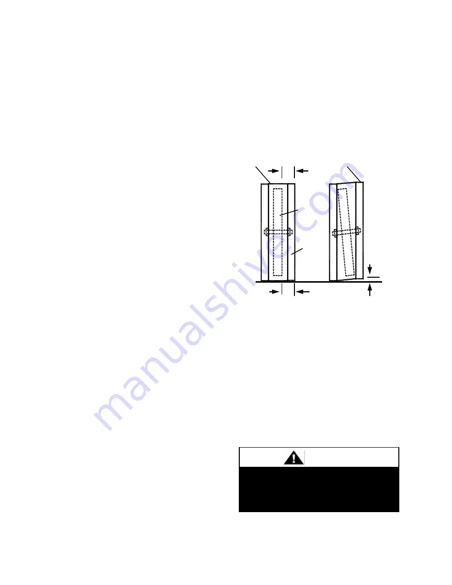
Avoid Racking of Cassette Frame
To verify, make certain that the distance
between wheel rim and bearing beam is the
same at each end of the bearing beam, to
within 1/4 of an inch (dimension A & B).
This amount of racking can be compensated
for by adjusting the diameter seals.
If greater than 1/4 inch (dimension C),
racking must be corrected to ensure that drive
belt will not disengage from wheel.
Polymer Wheel Startup Procedure
B
C
A
Bearing beams shown
racked
Frame
Wheel
Bearing
beams
(2)
Flat surf ace
Keep hands away from rotating wheel!
Contact with rotating wheel can cause
physical injury.
CAUTION
Summary of Contents for RZ Series
Page 2: ......
Page 31: ...31 Figure 4 4 Point Lift RZ Series Air Cooled Condenser Unit ...
Page 90: ...90 Gas Heater Operating Instructions ...
Page 108: ...108 Maintenance Log E Coated Coil ...
Page 110: ...110 ...
Page 111: ......


