77
1.
By hand, turn wheel clockwise (as
viewed from the pulley side), to verify
wheel turns freely through 360º rotation.
2.
Before applying power to drive motor,
confirm wheel segments are fully
engaged in wheel frame and segment
retainers are completely fastened. (See
Segment Installation Diagram).
3.
With hands and objects away from
moving parts, activate unit and confirm
wheel rotation. Wheel rotates clockwise
(as viewed from the pulley side).
4.
If wheel has difficulty starting, turn
power off and inspect for excessive
interference between the wheel surface
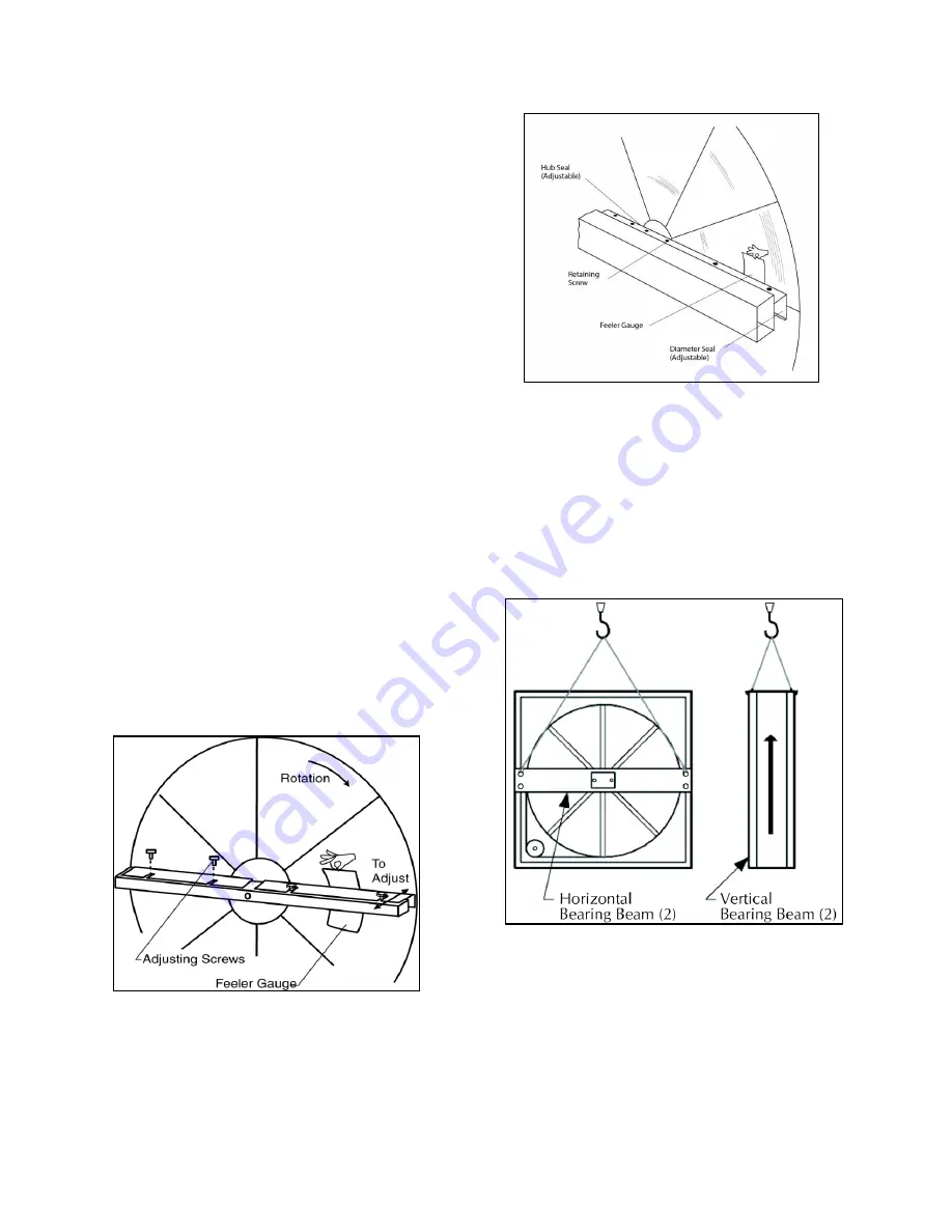
and each of the four (4) diameter seals.
To correct, loosen
diameter
seal
adjusting screws and back adjustable
diameter seals away from surface of
wheel, apply power to confirm wheel is
free to rotate, then re-adjust and tighten
hub and diameter seals, as shown in hub
seal adjustment diagram.
5.
Start and stop wheel several times to
confirm seal adjustment and to confirm
belt is tracking properly on wheel rim
(approximately 1/4” from outer edge of
rim).
Diameter Seal Adjustment
Hub Seal Adjustment
Polymer Wheel Routine Maintenance and
Handling
Handle cassettes with care. Lift all cassettes
by the bearing support beam. Holes are
provided on both sides of the bearing support
beams to facilitate rigging as shown in the
following illustration.
Lifting Hole Locations
Routine maintenance of the Energy Recovery
Cassettes includes periodic cleaning of the
Energy Recovery Wheel as well as inspection
of the Air Seals and Wheel Drive
Components as follows:
Summary of Contents for RZ Series
Page 2: ......
Page 31: ...31 Figure 4 4 Point Lift RZ Series Air Cooled Condenser Unit ...
Page 90: ...90 Gas Heater Operating Instructions ...
Page 108: ...108 Maintenance Log E Coated Coil ...
Page 110: ...110 ...
Page 111: ......


