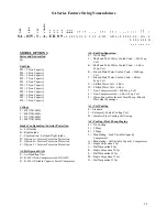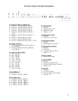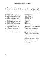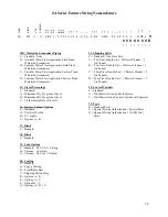
SA Series Feature String Nomenclature
GEN
S
IZ
E
V
L
T
C
ON
FIG
A1
A2
A3
A4
B1
B2
B3
1A
1B
1C
1D
2
3
4
5A
5B
5C
6A
6B
6C
7
8
9
10
11
12
13
14A
14B
15
SA - 035 - 3 - A - E R 0 9 -
0 0 0
:
A C 0 0 - 0 0 0 - E B F - A B 0
-
0 0 0 0 0 0 0 - H A - 0
0 0 0 0 0 0 0 B
16
17
18
19
20
21
22
23
11
SA Series Feature String No me nclature
MODEL OPTIONS
Series and Generation
SA
Unit Size
023 = 23 ton Capacity
028 = 28 ton Capacity
030 = 30 ton Capacity
035 = 35 ton Capacity
045 = 45 ton Capacity
050 = 50 ton Capacity
055 = 55 ton Capacity
058 = 58 ton Capacity
060 = 60 ton Capacity
065 = 65 ton Capacity
070 = 70 ton Capacity
Voltage
2 = 230V/3Φ/60Hz
3 = 460V/3Φ/60Hz
4 = 575V/3Φ/60Hz
8 = 208V/3Φ/60Hz
Intake Configuration / Interior Protection
A =
Left Intake
B =
Right Intake
C =
Combination - Left and Right Intake
D =
Option A + Interior Corrosion Protection
E =
Option B + Interior Corrosion Protection
F =
Option C + Interior Corrosion Protection
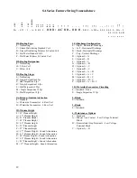
A1: Refrigerant Style
0 =
Air Handling Unit
B =
R-410A Non-Compressorized DX AHU
E =
R-410A Variable Capacity Scroll Compressor
A2: Unit Configuration
0 =
No Cooling
J =
Shell and Tube Water-Cooled Cond. + Std Evap.
Coil
K =
Shell and Tube Water-Cooled Cond. + 6 Row
Evap. Coil
R =
Brazed Plate Water-Cooled Cond. + Std Evap.
Coil
T =
Brazed Plate Water-Cooled Cond. + 6 Row
Evap. Coil
U =
Chilled Water Coil - 4 Row
W =
Chilled Water Coil - 6 Row
2 =
Non-Compress Std Evap. Coil
4 =
Non-Compress 6 Row Evap. Coil
8 =
Water-Source/Geothermal Heat Pump - Brazed
Plate Heat Exchanger
A3: Coil Coating
0 = Standard
1 = Polymer E-Coated Cooling Coil
D = Stainless Steel Cooling Coil Casing
A4: Cooling / Heat Pump Staging
0 =
No Cooling
2 =
2 Stage
4 =
4 Stage
9 =
Modulating - Lead Variable Capacity
Compressors
A =
Modulating - All Variable Capacity Compressors
H =
Single Serpentine 8 fpi
J =
Half Serpentine 8 fpi
K =
Single Serpentine 10 fpi
L =
Half Serpentine 10 fpi
M =
Single Serpentine 12 fpi
N =
Half Serpentine 12 fpi
Summary of Contents for SA-028
Page 2: ......
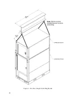
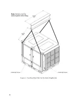
Page 20: ...20 Figure 2 One Piece Single Unit Lifting Details...
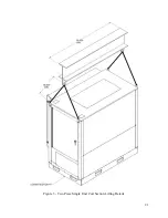
Page 21: ...21 Figure 3 Two Piece Single Unit Coil Section Lifting Details...
Page 22: ...22 Figure 4 Two Piece Single Unit Fan Section Lifting Details...
Page 23: ...23 Figure 5 One Piece Dual Unit Lifting Details...
Page 24: ...24 Figure 6 Two Piece Dual Unit Coil Section Lifting Details...
Page 25: ...25 Figure 7 Two Piece Dual Unit Fan Section Lifting Details...
Page 28: ...28 Figure 10 Dual unit with splices after being bolted together...
Page 63: ...63...


