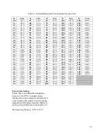
32
NOTE:
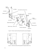
Ball valves should be installed in
the condenser water supply and return lines
for unit isolation and water flow balancing.
All manual flow valves should be of the ball
valve design. Globe or gate valves should
not be used due to high pressure drops and
poor throttling characteristics.
Pressure
and
temperature
ports
are
recommended in condenser water supply
and return lines for system balancing. These
openings should be 5 to 10 pipe diameters
from the unit water connections. To allow
for mixing and temperature stabilization,
wells in the water piping should extend at
least ½ pipe diameter into the pipe.
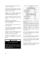
Table 4 - Condenser Pressure Drops (Each Heat Exchanger
)
SA-023
SA-028
SA-030
SA-035
GPM
PSI
GPM
PSI
GPM
PSI
GPM
PSI
45
4.2
45
4.2
45
4.2
45
1.7
39
3.3
39
3.3
39
3.3
39
35
2.8
35
2.8
35
2.8
35
SA-045
SA-050
SA-055
SA-058
GPM
PSI
GPM
PSI
GPM
PSI
GPM
PSI
45
4.2
45
4.2
45
4.2
45
4.2
39
3.3
39
3.3
39
3.3
39
3.3
35
2.8
35
2.8
35
2.8
35
2.8
SA-060
SA-065
SA-070
Heat Exchanger 1
Heat Exchanger 2
GPM
PSI
GPM
PSI
GPM
PSI
GPM
PSI
45
4.2
45
4.2
45
1.7
45
1.7
39
3.3
39
3.3
39
39
35
2.8
35
2.8
35
35
Each heat exchanger
may be
equipped with a refrigerant pressure
relief device to relieve pressure
should
excessive
condensing
pressures (>675 psig) occur.
Codes
may
require
installing
contractor to connect and route relief
piping outdoors. The relief valve has
a 5/8” male flare outlet connection.
CAUTION
Installing contractor is responsible for
properly sizing and installing water
system components. Improper fluid
flow due to valves, piping, or
improper pump operation may result
in unacceptable unit operation and
void warranty.
CAUTION
Summary of Contents for SA-028
Page 2: ......
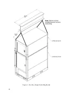
Page 20: ...20 Figure 2 One Piece Single Unit Lifting Details...
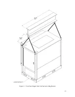
Page 21: ...21 Figure 3 Two Piece Single Unit Coil Section Lifting Details...
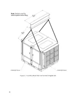
Page 22: ...22 Figure 4 Two Piece Single Unit Fan Section Lifting Details...
Page 23: ...23 Figure 5 One Piece Dual Unit Lifting Details...
Page 24: ...24 Figure 6 Two Piece Dual Unit Coil Section Lifting Details...
Page 25: ...25 Figure 7 Two Piece Dual Unit Fan Section Lifting Details...
Page 28: ...28 Figure 10 Dual unit with splices after being bolted together...
Page 63: ...63...


