43
Supply Fan Removal
1.
Disconnect all electrical power sources
to the unit.
2.
Disconnect the supply fans using the
quick connect electrical harness located
in the control compartment.
3.
Remove the three screws on the hold
down bracket on the front side of the fan
assembly frame.
4.
Remove the back fan access panel and
then remove the three screws on the rear
side of the fan assembly frame.
5.
Slide the complete fan assembly forward
through the front supply fan access door.
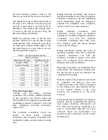
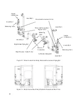
Figure 18 - Back View with Supply Fan
Access Panel Removed
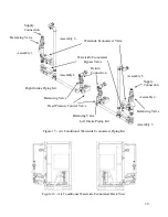
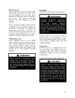
Figure 19 - Front View with Supply Fan
Access Door Open
Fan Airflow Adjustment
A specific air volume is delivered by the
fans with air volume bands in the blower
wheels or with VFDs. Field airflow
adjustment may be required at startup.
Air volume bands for the wheels are sized
according to the unit’s air delivery
specifications and can also be ordered from
the factory for field installation. Wheels
come standard with a 10% air volume band,
as a safety factor, in case additional air
volume is required from the unit.
Adjustment
If reduced air volume is required an air
volume band or larger air volume band can
be installed within the blower wheel to
reduce the amount of air delivered by the
wheel.
If the unit is factory equipped with the air
volume band and additional air volume is
Disconnect
all
electrical
power
sources before servicing the unit.
More than one power source may be
provided. Failure to do so may result
in injury or death from electrical
shock or entanglement in moving
parts.
WARNING
Hold Down
Bracket Screws
Hold Down
Bracket Screws
Summary of Contents for SA-028
Page 2: ......
Page 20: ...20 Figure 2 One Piece Single Unit Lifting Details...
Page 21: ...21 Figure 3 Two Piece Single Unit Coil Section Lifting Details...
Page 22: ...22 Figure 4 Two Piece Single Unit Fan Section Lifting Details...
Page 23: ...23 Figure 5 One Piece Dual Unit Lifting Details...
Page 24: ...24 Figure 6 Two Piece Dual Unit Coil Section Lifting Details...
Page 25: ...25 Figure 7 Two Piece Dual Unit Fan Section Lifting Details...
Page 28: ...28 Figure 10 Dual unit with splices after being bolted together...
Page 63: ...63...

