44
required, the band can be removed from the
wheel.
Use fan program in AAONEcat32 to
determine the new band size for the required
cfm and static pressure.
The following photos of a wheel are
provided for practical guidelines only in
order to identify the air band location in the
wheel. Actual field installation of the air
band into the wheel will require access into
and through the blower wheel venture,
which may require removal of the blower
motor and wheel.
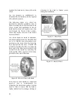
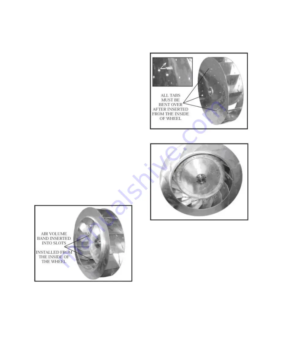
Air volume bands are made of aluminum,
sized and equipped with easy bend tabs that
are to be inserted into pre-punched slots
provided on the wheel. Once the band has
been inserted into the slots, it MUST BE
secured by bending the tabs over from the
back side of the wheel and also MUST BE
secured from the inside by connecting the
ends together with a pop-rivet in the holes
provided on the ends of the band.
Figure 20 - Blower Wheel with Band
If the band is field installed, a hand held
pop-rivet
tool
is
recommended
for
connecting the band ends together. Caution
must be taken to assure that the band is
tightly installed and no damage, denting or
alteration to the wheel or blades occurs
during the installation.
Figure 21 - Band Tabs
Figure 22 - Blower Wheel
Summary of Contents for SA-028
Page 2: ......
Page 20: ...20 Figure 2 One Piece Single Unit Lifting Details...
Page 21: ...21 Figure 3 Two Piece Single Unit Coil Section Lifting Details...
Page 22: ...22 Figure 4 Two Piece Single Unit Fan Section Lifting Details...
Page 23: ...23 Figure 5 One Piece Dual Unit Lifting Details...
Page 24: ...24 Figure 6 Two Piece Dual Unit Coil Section Lifting Details...
Page 25: ...25 Figure 7 Two Piece Dual Unit Fan Section Lifting Details...
Page 28: ...28 Figure 10 Dual unit with splices after being bolted together...
Page 63: ...63...

