background image

Advance AutoQuip 

2 McDonald Crescent | Bassendean WA 6054 

Ph: 08 9279 1663 | Fax: 08 9279 1667 | E: sales@aaq.net.au | W: www.aaq.net.au 

- READ THE ENTIRE CONTENTS OF THIS MANUAL BEFORE

INSTALLATION AND OPERATION. BY PROCEEDING YOU AGREE THAT 

YOU FULLY UNDERSTAND AND COMPREHEND THE FULL CONTENTS 

OF THIS MANUAL. FORWARD THIS MANUAL TO ALL OPERATORS. 

FAILURE TO OPERATE THIS EQUIPMENT AS DIRECTED MAY CAUSE 

INJURY OR DEATH.


Specifications subject to change without notice.


Note: While all due care and attention has been taken in the preparation of this document, Advance AutoQuip shall not be liable for any inaccuracies or omissions 

which may occur therein


4

 POST HOIST

AutoLift 

163027

Extra High 

4 Post 

Storage 

Vehicle Hoist  

320

0Kg Maximum Lifting Capacity


Design Registration Approval Number: 

N/A - Domestic Application

Design Code: AS1418.9-1996

6

INSTALLATION MANUAL & OPERATION 

INSTRUCTIONS

READ FIRST 

DO NOT use the 

machine until you read 

and understand all the 

dangers, warnings and 

cautions in this manual.


Summary of Contents for AutoLift 163027

Page 1: ...JURY OR DEATH Specifications subject to change without notice Note While all due care and attention has been taken in the preparation of this document Advance AutoQuip shall not be liable for any inaccuracies or omissions which may occur therein 4 POST HOIST AutoLift 163027 Extra High 4 Post Storage Vehicle Hoist 3200Kg Maximum Lifting Capacity Design Registration Approval Number N A Domestic Appl...

Page 2: ...ant Concrete and Anchoring Information Page 6 Installation and Basic Operation Instruction Page 7 Safety Procedures Page 14 Maintenance Schedule Page 15 Troubleshooting Page 17 Owners Responsibilities Page 18 Packing list Page 19 Installation specification Page 20 Parts drawing Page 21 Parts code list Page 26 ...

Page 3: ...damage to the hoist yourself or other property The hoist is intended to lift vehicles only It is not designed to lift any person or equipment containing persons All persons using this equipment should be qualified responsible persons and should follow the operation and safety guidelines set forth in this manual For specifications on concrete pads please call for technical assistance Improper insta...

Page 4: ...kness and 3000psi tensile strength concrete sufficiently cured This is a vehicle hoist installation operation manual and no attempt is made or implied herein to instruct the user in lifting methods particular to an individual application Rather the contents of this manual are intended as a basis for operation and maintenance of the unit as it stands alone or as it is intended and anticipated to be...

Page 5: ...te of the columns 2 There are no cracks within 965mm and no seams within 150mm of the base plate 3 The concrete is recommended with following dimension 4000mm L 1000mm W 200mm H Remember any structure is only as strong as the foundation on which it is located 4 Check for ceiling clearance Suggestion At least 127 mm left between the top of a car on the hoist and the ceiling Check for clearance in t...

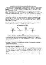
Page 6: ...torque replace concrete under each column base with a 1220 x 1220 x 150 thick 3 000 PSI minimum concrete pad keyed under and flush with the top of existing floor Let concrete cure before installing lifts and anchors ANCHORING TIP SHEET Fig 1 Anchors must be at least 150cm from the edge of the slab or any seam 1 Use a concrete hammer drill with a carbide tip solid drill bit the same diameter as the...

Page 7: ...y inspect the site where the hoist is to be installed and check for cracked or defective concrete 4 FLOOR REQUIREMNETS The hoist should be installed on a 3000 PSI concrete with little gradients Fig 2 Location checking IMPORTANT NOTICE These instructions must be followed to insure proper installation and operation of your hoist Failure to comply with these instructions can result in serious bodily ...

Page 8: ...he posts on the floor at each location using the post base plates as a template 5 Double check all dimensions and make sure that the layout is perfectly square 6 Before continuing with the installation it is helpful to stand the posts up at their respective locations and get a visual of the shop aisles and other clearances Also this is a good time to drive a vehicle into position and check for ade...

Page 9: ...s at the right side Be sure that the utility rails for tool case located inside Fig 10 Fig 10 Fig 11 Fig 12 2 Using bolts provided bolt the right rear end of the off side runway on the rear cross bar The other end is free Fig 11 3 Before locating the power side runway on the cross bar pull out the cables underneath and check them over the pulleys The shortest one is for the power side column The l...

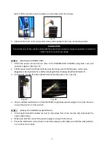
Page 10: ...ct the oil hose from the cylinder hose end to the power unit Fig 20 Fig 19 Fig 20 4 Have a certified electrician to run the 240V 50Hz single phase power supply to the motor Be sure to size the wire for a 15 amp circuit STEP 7 Routing the CABLES and SAFE RACK 1 Check again that all the cables are rest on the pulleys both of the columns and underneath the power side runway 2 Make sure that the curre...

Page 11: ...P 9 Hoist start up 1 Do not place any vehicle on the hoist at this time 2 Connect the elec power supply to the motor pump Connect the compressed air supply to the air valve 3 Cycle the hoist up and down several times to insure latch click together and all air is removed from the system 4 To lower the hoist the air valve must be manually hold down while the lowering handle of the pump is pressed Lo...

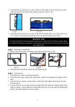
Page 12: ...prevent bending the column base plates 5 With the shims and anchor bolts in place tighten by securing the nut to the base then turning 2 3 full turns clockwise DO NOT use an impact wrench for this procedure 6 Using the lever again check the cross bar for front and rear Fig 22 If need loose the bottom bolt of the safety rack Turn the rack nut on the top of the column to raise the lower end of the c...

Page 13: ...nt stops and ramps 2 Drive the vehicle on the ramps Take off the ramps and lock the vehicle by insert stops under the wheels Check again the vehicle on the hoist is safe 3 Raise up the hoist to its highest position 4 Drive another vehicle under the hoist Fig 38 Fig 38 ...

Page 14: ... hoses shop equipment z When approaching the hoist with a vehicle center the vehicle wheel on the runway Slowly drive the vehicle up on the runways Have some one outside the vehicle guide the driver z Never use hoist to raise one end or one side of vehicle z Raise vehicles about 900mm and check stability by light rocking z Prior to lowering vehicle walk around the hoist and check for any objects t...

Page 15: ...and even death z Check safety lock audibly and visually while in operation z Check safety latches for free movement and full engagement with rack z Check hydraulic connections and hoses for leakage z Check cables connections bends cracks and looseness z Check for frayed cables in both raised and lowered position z Check snap rings at all rollers and sheaves z Check bolts nut and screws and tighten...

Page 16: ...rs z Replace cables and sheaves z Replace or rebuild air and hydraulic cylinders as required z Replace or rebuild pumps motors as required z Check hydraulic and air cylinder rod and rod end threads for deformation or damage z Check cylinder mount for looseness and damage Relocating or changing components may cause problems Each component in the system must be compatible an undersized or restricted...

Page 17: ...t run A Impeller fan caver is dented Take off and straighten B Faulty wiring call electrician C Bad capacitor call electrician D Low voltage call electrician E Hoist overloaded 5 Hoist jerk going up and down air in hydraulic system Raise hoist all the way to top and return to floor Repeat 4 6 times with 2 min rest every time Do not let this overheat power unit 6 Oil leaks A Power unit if the power...

Page 18: ...before beginning any hoist repairs Shall not modify the hoist in any manner without prior written consent of the manufacturer Shall display the operating instructions and Lifting It Right and Safety Tips supplied with the hoist in a conspicuous location in the hoist area convenient to the operator Shall insure that hoist operators are instructed in the proper and safe use and operation of the hois...

Page 19: ... bar 1 5 Power side column 1 With mounting holes for pump 6 Off side column 3 7 wheel stop 4 8 Approach ramp 2 9 Beam cover 4 10 Accessory box 1 Anchors and shims 11 Electro hydraulic pump 1 ITEM MODEL 163027 Overall Length 5360mm Overall Width 3835mm Overall Height 4293mm Between Columns Inside Length 4788mm Between Columns Inside Width 3226mm ...

Page 20: ...20 INSTALLATION SPECIFICATION OF PARKING HOIST 163027 Fig 40 485mm 1185 1612mm 3820mm 3220mm 4660mm 6360mm 5260mm 4190mm 4300mm Min180mm Max3680mm 5200mm ...

Page 21: ...21 PARTS DRAWING OF 163027 PARKING HOIST Fig 41 1 2 3 4 34 10 11 13 14 15 16 17 18 19 20 21 94 24 25 26 27 22 23 1 6 28 8 9 5 7 1 7 2 7 30 31 29 32 33 ...

Page 22: ...22 PARTS DRAWING OF 163027 PARKING HOIST safety lock system Fig 42 74 75 76 77 78 79 38 39 40 41 47 43 44 42 45 46 37 48 49 27 56 55 54 50 51 52 53 72 71 70 69 61 68 67 66 64 63 62 65 ...

Page 23: ...23 PARTS DRAWING OF 163027 PARKING HOIST cylinder and motor pump connection Fig 43 8 2 8 1 6 0 7 5 5 8 5 7 8 0 5 9 7 4 7 3 7 5 5 5 7 4 ...

Page 24: ...24 PARTS DRAWING OF 163027 PARKING HOIST cable wiring Fig 44 1 3 8 6 8 1 0 6 8 5 1 0 3 1 0 2 4 1 0 0 8 3 1 0 1 4 5 8 4 ...

Page 25: ...25 PARTS DRAWING OF 163027 PARKING HOIST Fig 45 95 110 111 112 107 106 93 91 92 89 87 98 99 88 97 96 108 109 ...

Page 26: ...01 013 nut 40 M8 14 163027 01 014 flat washer 34 d8 15 163027 01 015 bolt 4 M8X25 16 163027 01 016 spring washer 14 d8 17 163027 01 017 bolt 4 M10X70 18 163027 01 018 front stop 2 19 163027 01 019 washer 1 20 163027 01 020 connector 1 21 163027 01 021 elbow connector 1 22 163027 01 022 screw 13 M6X10 23 163027 01 023 hose holder 1 24 163027 01 024 bolt 10 M10X40 25 163027 01 025 washer 2 26 163027...

Page 27: ... 53 163027 03 053 sleeve 3 1 L 34 54 163027 03 054 fixing board 6 55 163027 03 055 air cylinder 4 56 163027 03 056 jointing board 4 57 163027 05 057 T connector 2 2 58 163027 05 058 T connector 1 1 59 163027 05 059 elbow connector 4 60 163027 05 060 air hose 1 61 163027 03 061 safety bar 4 62 163027 03 062 nut 40 M8 63 163027 03 063 washer 34 d8 64 163027 03 064 spring 8 65 163027 03 065 split pin...

Page 28: ...10 86 163027 06 086 cable 4 1 L 11320 89 163027 06 089 connector 1 91 163027 07 091 cscrew 4 M6X8 92 163027 07 092 flat washer 14 d6 93 163027 07 093 Circlip 1 d30 94 163027 01 094 hose 1 L 6m 95 163027 07 095 shaft 2 96 163027 07 096 limit screw 4 97 163027 07 097 fixing board 100 163027 06 100 socket screw 2 M10X30 101 163027 06 101 board 1 102 163027 06 102 dolly 2 103 163027 06 103 dolly 1 106...

Page 29: ...the capacity of the hoist compared to the weight of the vehicle If vehicle is too heavy do not proceed 4 Ensure the area is clean and clear of grease oil and objects that may be a slip trip hazard 5 Familiarise yourself with and check all machine operations and controls 6 Check all safety devices are in good condition 7 Ensure support arms are capable of being locked in position 8 Ensure rubber pa...

Page 30: ...MENT IS NOT TO BE USED FOR WASH DOWN PURPOSES OR TO BE INSTALLED IN AN OUTDOOR ENVIRONMENT WHERE IT IS SUBJECT TO WEATHER OR WATER DAMAGE WARRANTY WILL BE IMMEDIATELY VOID STRUCTURAL COMPONENTS ALL STRUCTURAL AND MECHANICAL COMPONENTS OF THIS UNIT ARE GUARANTEED FOR A PERIOD OF FIVE YEARS FROM THE DATE OF INVOICE AGAINST DEFECTS IN MATERIALS WHEN LIFT IS INSTALLED AND USED ACCORDING TO RECOMMENDAT...

Page 31: ...ety locks tested for correct operation Checked for good working order Supplied with the hoist and in good working order Checked for correct operation Hoist checked with load for correct operation and speed control tested Checked wire ropes for correct installation and tension Concrete floor is a suitable depth for installation Safety Devices Welds Hydraulic Equipment and Controls Pneumatic Equipme...

Page 32: ...onstrated the operation of the vehicle hoist to the owner or operator Lock off isolating switch installed Emergency stop button installed 3 Details of Electrical Contractor Trading Name Address 4 Signature I being the person responsible for completing the commissioning report have exercised reasonable skill and competency when completing the report and herby certify that the vehicle hoist has been...

Reviews: