9
Fig. 4 power-side column
Fig. 5
Fig. 6
5.
Bolt the safety rack on both end. (Fig. 7 & 8 )
6.
Raise up the cross bar ends to rest on the first (lowest) position. (Fig. 9)
Fig.7
Fig. 8
Fig. 9
7.
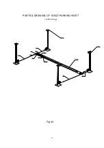
Again check all the position of the columns according to the drawings. Using a tape measure to
measure the distance between the opposite corners of the base plate on the columns. Equal
values will insure the lifting arms will be in square.
STEP 5
: (Mounting the runway)
1. Put the sub runway on the cross bars at the right side. Be sure that the utility rails for tool case
located inside. (Fig. 10)
Fig. 10
Fig.11
Fig.12
2. Using bolts provided, bolt the right-rear end of the off-side runway on the rear cross bar. The other
end is free. (Fig. 11)
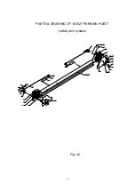
3. Before locating the power-side runway on the cross bar, pull out the cables underneath and check
them over the pulleys. The shortest one is for the power-side column. The longest one is for the
opposite. Put the power-side runway on the cross bars. (Fig. 12)
4. Put the cables through the runway and the pulley, going up to the top board of the column and bolt
them (Fig 14, 15). Be sure that the cable is against the small roller so that the emergency locking


