background image

18

Summary of Contents for AutoLift AL-6000S2

Page 1: ...ON AND OPERATION BY PROCEEDING YOU AGREE THAT YOU FULLY UNDERSTAND AND COMPREHEND THE FULL CONTENTS OF THIS MANUAL FORWARD THIS MANUAL TO ALL OPERATORS FAILURE TO OPERATE THIS EQUIPMENT AS DIRECTED MAY CAUSE INJURY OR DEATH Specifications subject to change without notice Note While all due care and attention has been taken in the preparation of this document Advance AutoQuip shall not be liable fo...

Page 2: ...ONLY BE PERFORMED BY COMPETENT PERSONNEL OPERATION OF THE HOIST MUST ONLY BE PERFORMED BY TRAINED PERSONNEL THIS HOIST MUST ONLY BE USED FOR THE PURPOSE OF LIFTING MOTOR VEHICLES WITH A WEIGHT OF NO MORE THAN 6000KG THIS MANUAL MUST BE KEPT IN A SAFE PLACE FOR FUTURE REFERENCE SERVICING MAINTENANCE OF THE HOIST IS THE OWNERS RESPONSIBILITY 1 ...

Page 3: ... the hoist to lift only one side of a vehicle Ensure the vehicle is correctly positioned on the hoist platforms before operation 3 DO NOT modify any component of the hoist 4 All personnel must remain clear of the hoist during the raising lowering of the vehicle 5 All personnel must keep their feet clear of the hoist during lowering 6 No objects are to be placed under the vehicle during the raising...

Page 4: ...t around the hoist Ensure the vehicle is loaded centrally on the hoist before operation The vehicle handbrake must be engaged before operating the hoist Ensure that the safety is engaged before working under hoist Stop raising the hoist if the platforms become unbalanced If a vehicle becomes unstable on the hoist vacate the area immediately Do not use the hoist for any purpose other than lifting a...

Page 5: ... carry out lifting transport assembling installation adjustment calibration settings extraordinary maintenance repairs overhauling and dismantling of the hoist THE MANUFACTURER IS NOT RESPONSIBLE FOR POSSIBLE DAMAGE TO PEOPLE VEHICLES OR OBJECTS IF SAID OPERATIONS ARE CARRIED OUT BY UNAUTHORIZED PERSONNEL OR THE HOIST IS IMPROPERLY USED Any use of the machine by operators who are not familiar with...

Page 6: ...ers from that provided by the manufacturer of the machine is strictly forbidden The use of non genuine parts may cause damage to people or objects DECLARATION OF WARRANTY AND LIMITATION OF LIABILITY The manufacturer has paid proper attention to the preparation of this manual However nothing contained herein modifies or alters in any way the terms and conditions of manufacturer agreement by which t...

Page 7: ...rictly forbidden Machines may be updated or slightly modified from an aesthetic point of view and as a consequence they may present different features from these shows without prejudicing what has been described herein Warranty certificate The warranty is valid for a period of 12 months starting from the date of the purchase invoice The warranty will come immediately to an end when unauthorized mo...

Page 8: ... time Storage and stacking of packages Packages must be stored in a covered place out of direct sunlight and in low humidity at a temperature between 10 and 40 Stacking is not recommended the package s narrow base as well as its considerable weight and size make it difficult and hazardous Delivery and check of packages When the hoist is delivered check for possible damages due to transport and sto...

Page 9: ...l the supplied technical literature in a safe place close to the hoist in order to help the users to consult it whenever necessary The technical literature is an integral part of the hoist and it must always follow the product even in case of sale Follow the directions given by this guide with the utmost attention the Constructor declines all responsibility for any damage due to negligence and non...

Page 10: ...Dimensions AL 6000S2 9 ...

Page 11: ...h and Safety at Work regulations for instance with respect to minimum distance to wall or other equipment escapes and the like must be observed Lighting Lighting must be carried out according to the effective regulations of the place of installation All area next to the hoist must be well and uniformly light Installation surface The hoist must be placed on level floor and sufficiently resistant Th...

Page 12: ...and expansion joints in the concrete doing this could effect the safe installation of the hoist The concrete must Have a minimum thickness of 200mm Be Reinforced Be a grade of no less than 25MPA Tools Required For the installation of the hoist you will require the following Rotary hammer drill 16mm Masonry drill bit Chalk line Spirit Level General tool Kit Unpacking The hoist is supplied in a purp...

Page 13: ...sition a qualified electrician can now connect the electrical wiring to the control box 7 The platforms and transverse beams need to be assembled into position Due to the control post already being bolted into place it is important that the hoist is built from that point 8 Using 200mm high suitable blocks of timber locate the transverse beams into position on the timber noting that there is a fron...

Page 14: ...icture 2 15 Once the posts are in position locate the bottom of the safety ladder into the hole at the bottom of the post ensuring the locating tab on the end of the safety ladder is not contacting with the concrete Secure the safety ladder to the top of the post using the nuts supplied See Picture 3 16 Feed the wire cables from the transverse beam to the top of each post and secure the thread wit...

Page 15: ...e ground 26 Check that all posts are in the correct position ensuring that they are square to each other as well as horizontally level Depending on the install situation the posts may need to be shimmed Before bolting it is also important to ensure that the posts are vertically level in both planes 27 Once all posts are correctly positioned and level they are ready to be bolted 28 Drill the 4 x 16...

Page 16: ...stment has been completed check the synchronisation of the locks with a vehicle on the hoist If necessary re adjust the cables 35 Place the post caps on top of all posts Assembly Pictures Picture 1 Picture 2 Picture 3 Picture 4 Picture 5 Picture 6 Picture 7 Chamfer 15 ...

Page 17: ... The Cam Locks must prevent the hoist from lowering once the floor jack is lowered 5 Repeat this above steps for the rear of the hoist also Electrical Connection PLEASE NOTE All electrical work on the hoist including motor connection mains supply connection must Only be performed by a qualified electrician Important Information It is the installers responsibility to ensure that all Fasteners Nuts ...

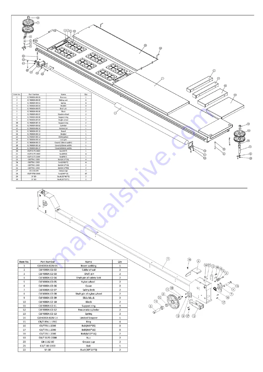
Page 18: ...Parts List 17 ...

Page 19: ...18 ...

Page 20: ...HYDRAULIC UNIT 1 MOTOR 2 RELIEF VALVE 3 SUPPORT 4 SUPPORT BOLT 5 HYDRAULIC HOSE 6 BREATHER CAP 7 DRAIN CAP 8 SOLENOID VALVE SET 1 2 3 4 5 6 7 8 19 ...

Page 21: ...E 4 RAIL GUIDE 5 LINK 2 6 BASE 7 RAIL 10 ONE TOUCH HOSE COUPLER 11 STOPPER 1 2 3 4 5 6 7 8 9 10 11 12 13 14 15 16 17 18 19 20 12 STOPPER PIN 13 MIDDLE LINK PIN 14 ROD 15 ROD COVER 16 HEAD SEAL KIT 17 PISTON 18 PISTON SEAL KIT 19 TUBE 20 TAIL COVER 20 ...

Page 22: ...t time 25s Max lifting height 1750mm 1700mm Min lifting height 268mm Overall width 3303mm Overall height 2164mm Drive through 2993mm Power supply 240V 50 Hz 1PH 415V 50HZ 3PH Motor 2 2 KW Noise 85dB Installation place Indoors Net Weight 2100kgs 1770kgs Gross Weight 2150kgs 1820kgs Safety catch type Pneumatic Jack lifting capacity 3000kg Jack lifting height 450mm 21 ...

Page 23: ...d around the hoist Part No Part Name 1 Control Panel 2 Power Lamp 3 Power Switch 4 Up Button 5 Lock Button 6 Down Button Switch Box Operation 1 Use the up button to raise the hoist 2 Use the lock button to lower the hoist to the next safety lock 3 Use the down button to lower the hoist During this operation the hoist will automatically raise to clear the safety locks before lowering 22 ...

Page 24: ...Hydraulic system diagram 1 Motor 2 Parachute Valve 3 Unloading valve 4 Descend speed regulating valve 5 Relief valve 6 Gear pump 7 Check valve 23 ...

Page 25: ...Air Line Diagram 24 ...

Page 26: ...Electric motor jumper pins 25 ...

Page 27: ...26 ...

Page 28: ...How to operate Jack 27 ...

Page 29: ...d check limit switch position if ok check oil level add oil Fill up through the filler cap using 32 45 viscosity hydraulic oil Check tension of foundation bolts dyne bolts 9 1 2 EVERY MONTH Check tightening of screw Check the hydraulic system seal and tighten the loose unions if necessary Check the hydraulic hoses condition In case they are worn replace them by new hoses of the same kind Check the...

Page 30: ...or any leakage The hoist does not lower when the DOWN button is pressed The lowering solenoid valve does not work properly Verify if it is powered and check magneto for damage replace if disconnected or blown Safety solenoid valve is jammed Verify if it is powered and check magneto for damage replace if disconnected or blown The DOWN button is faulty Replace the DOWN button Carriages do not stop i...

Page 31: ... UNDER HOIST WHILE PERFORMING THIS PROCEDURE PROCEDURE IF YOU HAVE ANY DOUBT FOR PERFORMING THIS OPERATION CONTACT TRAINED PERSONNEL Emergency Decending AFTER COMPLETION REPOSITION ALL THE BOLTS AND NUTS INCLUDING EMERGENCY COCK VALVE TO ITS ORIGINAL POSITION AND COVER THE PANEL FOLLOW SAME PROCEDURE FOR JACK BRIDGES AS ABOVE 1 MAKE SURE THE SAFETY LOCK ON JACK BRIDGE IS CANCELLED If it is engaged...

Page 32: ...height is obtained checking for any obstructions 2 Once the hoist has reached the desired working height lower the hoist onto the safety locks by means of pressing the park button on the control box Note Check for correct engagement of each lock TO LOWER THE HOIST 1 Raise the hoist 100mm or until the locks are clear 2 Push on the DOWN button Note The hoist will automatically raise approximately 50...

Page 33: ...the capacity of the hoist compared to the weight of the vehicle If vehicle is too heavy do not proceed 4 Ensure the area is clean and clear of grease oil and objects that may be a slip trip hazard 5 Familiarise yourself with and check all machine operations and controls 6 Check all safety devices are in good condition 7 Ensure support arms are capable of being locked in position 8 Ensure rubber pa...

Page 34: ...GAINST DEFECTS IN WORKMANSHIP AND OR MATERIALS WHEN LIFT IS INSTALLED AND USED ACCORDING TO RECOMMENDATIONS POWER UNIT POWER UNIT COMPONENTS PUMP AND RESERVOIR ARE GUARANTEED A PERIOD OF TWO YEARS FROM THE DATE OF INVOICE AGAINST DEFECTS IN WORKMANSHIP AND OR MATERIALS WHEN THE LIFT IS INSTALLED AND USED ACCORDING TO RECOMMENDATIONS ELECTRICAL COMPONENTS ALL ELECTRICAL COMPONENTS INCLUDING MOTOR A...

Page 35: ...ety locks tested for correct operation Checked for good working order Supplied with the hoist and in good working order Checked for correct operation Hoist checked with load for correct operation and speed control tested Checked wire ropes for correct installation and tension Concrete floor is a suitable depth for installation Safety Devices Welds Hydraulic Equipment and Controls Pneumatic Equipme...

Page 36: ...onstrated the operation of the vehicle hoist to the owner or operator Lock off isolating switch installed Emergency stop button installed 3 Details of Electrical Contractor Trading Name Address 4 Signature I being the person responsible for completing the commissioning report have exercised reasonable skill and competency when completing the report and herby certify that the vehicle hoist has been...

Reviews: