10
arrow B are the auxiliary platform mounting holes. Four of the holes are also used
according to the platform space to install the sub-platform.
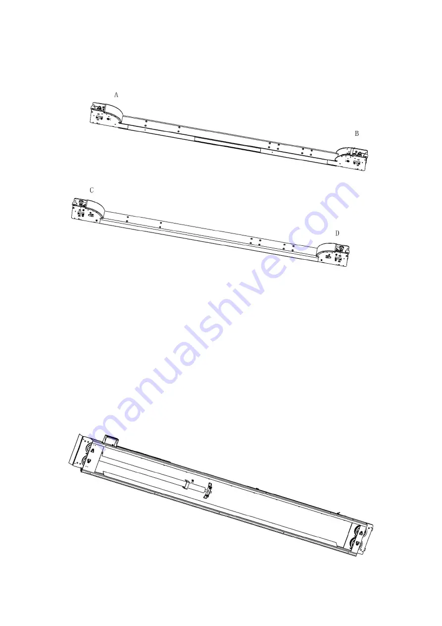
The specific placement of the beam is shown below:
In the figure above, the beams at points A and B are the main beams; the beams at
points C and D are the auxiliary beams, where the main pillar is placed at point A and
the auxiliary pillars are placed at the remaining points B / C / D; The four mounting
holes of the main beam and the auxiliary beam are where the main platform is
installed, and the eight mounting holes are where the auxiliary platform is installed.
Do not make a mistake according to the figure above.
When connecting to the platform, firstly place 4 equal height pads at the bottom of the
beam (two horizontally below each beam) with a height of more than 150mm; adjust
to the distance between the inner edges of the two beams of about 5010mm (5Tons) or
about 4296mm (4Tons); and the two ends of the beam are basically flush, that is, the
horizontal deviation of the two ends of points A and C, and the points of B and D does
not exceed 5mm).
The main platform (with oil cylinder and pulley inside the platform) is shown below:
Summary of Contents for SXJS4019A
Page 9: ...8 Top view of steel rope general arrangement ...
Page 43: ...10 2 2 Warning mark ...
Page 55: ...22 ...
Page 56: ...23 Chapter 7 Hydraulic System 7 1 Hydraulic pressure principle drawing ...
Page 60: ...29 ...
Page 61: ...30 ...
Page 62: ...31 ...
Page 63: ...32 ...
Page 64: ...33 ...
Page 65: ...34 ...


