Page 11
Aarrow Sherborne GSL CF
INSTALLATION INSTRUCTIONS
FITTING THE FLUE SPIGOT AND
BLANKING PLATE
Note: Blanking plate is fitted to top flue
outlet for packing
The gas stove is designed so that the flue
can be fitted to either the top or the rear of
the appliance.
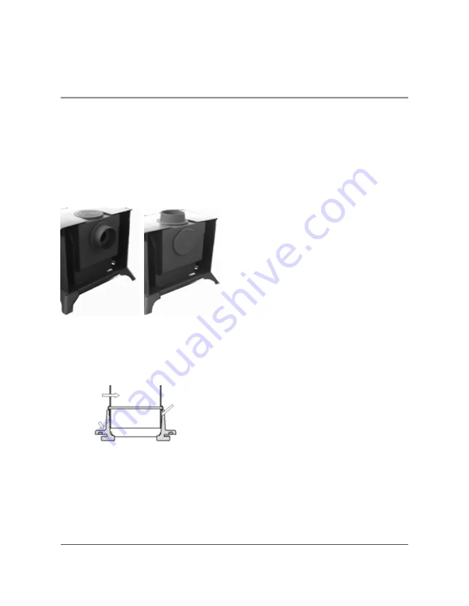
Fit the flue spigot and blanking plate for
either top or rear flue outlet in accordance
with
Figure 5a or 5b
below.
Fig. 5a
Fig. 5b
Lock the blanking hot plate in place by
rotating anti-clockwise and tighten by
tapping gently with a block of wood and
mallet. Fit the spigot to the unused opening
in the same way. The units are sealed by
the attached gaskets.
Seal All Round
Flue Spigot
Flue
Connection
CLOSURE PLATES
If a closure plate is used for sealing off the
chimney or fireplace it can be made of
metal (e.g. aluminium sheet) or fireplace
board (see fig 6 a/b/c on page 12) however
Fig. 5c
Provision must be made for checking for debris
build up. Closure plates must be sealed to the
chimney or fireplace opening with fire cement,
fireproof rope or other suitable high temperature
mastic.
REAR FLUE OPTIONS
Open Hearth (See Figure 6a page 12)
Fit and seal a „T‟ section (with debris / soot
collector) directly into the flue spigot. Ensure it
passes through the closure plate by at least
102mm (4”).
The maximum horizontal section allowed is
350mm.
Provide a minimum vertical height of 600mm of
flue from the height of the rear flue outlet
Closure Plate (See Figure 6b page 12)
Connect the flue spigot to the rear outlet then
connect a flue extension to the spigot up to a
maximum length of 350mm.
Fit and seal the closure plate into the fireplace
opening.
Position the stove so the flue extension passes
through the hole in the closure plate by at least
50mm.
Ensure all joints are sealed with fire cement or a
suitable high temperature sealant.
TOP FLUE OPTIONS
Top Flue (See Figure 6c page 12)


