background image


21

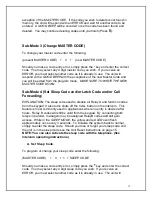
is presently disabled.  The unit will then issue a 

GOOD BEEP

 and wait for the 

master code.  If you wish to Activate the 3 strikes your out state, enter the master 
code.  If you do not wish to Activate the state, enter 

#

 to exit. 


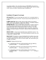
Sub-Mode 9 (Program Event Input) 


EXPLANATION:

  The event input allows the user to tie in an external device to 

control specific functions of the unit.  The event input can be programmed in 1 of 
5 ways. 
 

REMOTE INACTIVE:

 Relay A codes may be made inactive by an external 

switch.  When inactive all relay A codes will be disabled.  The relay B, program, 
and function codes will still be accessible to the end user. 

ARMING CIRCUIT:

  This is normally used to allow access in parking situations.  

An external vehicle detector may be connected to the input.  Relay A codes 
would only become active on the prescence detect of a vehicle.  If an entry 
attempt to activate relay A is made while the input is not activate, entry will be 
denied.  The relay B, program, and function codes will still be accessible to the 
end user. 
 

REMOTE OPEN:

  A relay may be activated using a pushbutton or switch.  The  

relay to activate is user selectable.  This function operates even when the unit is 
in sleep, latch, or program mode. 
 

NIGHT LIGHT:

 This will turn on the unit night light for 60 seconds using a relay 

connected to a loop detector, electric eye, motion sensor, etc. You must  move 
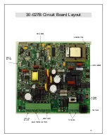
the Lights  jumper from On to Event to use this output. See circuit board layout 
on page 7 for location.  
 

DISABLE:

  Disables the Event Input. 


a)  To program the event input  as Remote Inactive enter the following; 


(MASTER CODE)    +    9 (*current event mode)    +    1 


b)  To program the event input  as an Arming Circuit enter the following; 


(MASTER CODE)    +    9 (*current event mode)    +    2 


c)  To program the event input  as Remote Open enter the following; 

(MASTER CODE)    +    9 (*current event mode)    +    3    +    (*Relay to 
Activate) 


Summary of Contents for PhoneLink 500

Page 1: ...Installation and Programming Instructions for PhoneLink 500 Model 16 2050...

Page 2: ...ess Codes 16 Sub Mode 2 Delete Codes 16 Sub Mode 3 Change MASTER CODE 17 Sub Mode 4 Set Sleep Code and or Latch Code and or Call Forwarding 17 Set Latch Code 18 Sub Mode 5 Set One Shot Code 19 Sub Mod...

Page 3: ...or installer of the product and return your AAS product along with the receipt to them If you have problems locating the dealer or installer contact American Access Systems at 303 799 9757 and we wil...

Page 4: ...ne network or premises wiring using a compatible modular jack which is Part 68 compliant See installation instructions for details 5 If this equipment causes harm to the telephone network the telephon...

Page 5: ...nctions may give the telecommunications company cause to request the user to disconnect the equipment Users should ensure for their own protection that the electrical ground connections of the power u...

Page 6: ...Please follow the instructions in this manual carefully to prevent problems during installation and programming 5 American Access Systems cannot guarantee compatibly with all telephones and accessorie...

Page 7: ...by field technicians to trouble shoot problems by plugging a standard RJ 11 jack phone into the test jack This is very helpful when working alone 3 Both diagrams also show an EVENT terminal block on...

Page 8: ...Link 500 see Diagram on page 10 for relay location In most installs this relay will connect to the OPEN circuit of a gate operator or connect in series with a DOOR STRIKE power lead Consult your acces...

Page 9: ...ink 50 Circuit Board Bypass Switch Telco Box Phone Company Phone Company To Phones House Phones Earth Ground PHONE COMPANY HOUSE PHONES T I P R I N G T I P R I N G N O COM N C N O COM N C RELAY A RELA...

Page 10: ...10 30 027B Circuit Board Layout PBX JUMPER RESET BUTTON LIGHTS JUMPER BYPASS SWITCH TEST JACK 12 VOLTS EVENT INPUT AC or DC TIP RING RELAY CONTROL OUTPUTS SETUP BUTTON...

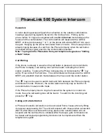
Page 11: ...ng tone will be heard indicating the control station is calling To place the Phone Company line on hold press the key within 15 seconds of the first tone The control station will respond with a GOOD B...

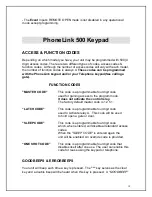
Page 12: ...leep code MUST be programmed into the PhoneLink before using the sleep command see page 17 5 Toggles ONE SHOT ENABLE mode on or off A double beep after the command indicates One Shot Enable is inactiv...

Page 13: ...r gaining access to the program mode It does not activate the control relay The factory default master code is 1 2 5 1 LATCH CODE This code is a programmable four digit code used to Activate relay A T...

Page 14: ...en a Unit Reset is performed the master code will be set back to 1 2 5 1 A Unit Reset is provided to reset the unit back to the initial factory state After a Unit Reset has been performed the unit wil...

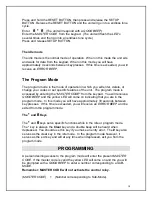
Page 15: ...the keypad You will receive a GOOD BEEP and the yellow LED will come on indicating that you are in the program mode In this mode you will have approximately 30 seconds between key presses If this time...

Page 16: ...MASTER CODE 1 NEW CODE NEXT NEW CODE etc to exit Should you make a code entry error simply press the key and enter the correct code You may select any 4 digit code you wish If you receive an ERROR af...

Page 17: ...p code used to disable all Relay A and function codes from the keypad It also turns shuts off the CALL button on the intercom This feature is most commonly used in applications where no entry is desir...

Page 18: ...nter the following MASTER CODE 4 2 LATCH CODE Should you make a code entry error simply press the key and enter the correct code You may select any 4 digit latch code you wish If you receive an ERROR...

Page 19: ...e ONE SHOT CODE is programed in you must enable it after each use NOTE The ONE SHOT CODE must be programmed first After the 5 is pressed the enable disable status is heard one beep enabled two beeps d...

Page 20: ...becomes full You will automatically be exited from the program mode if the memory reaches capacity When memory is full you will not be able to enter this Sub Mode and will receive an ERROR if entry is...

Page 21: ...ence detect of a vehicle If an entry attempt to activate relay A is made while the input is not activate entry will be denied The relay B program and function codes will still be accessible to the end...

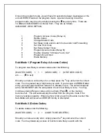
Page 22: ...Open input you will be prompted for which relay to activate on an event Enter the correct relay as stated above Relay to Activate Sub Mode 0 Erase all codes To erase all access function codes except...

Page 23: ...stomer service personnel technicians assist you with any problems you have E Mail customerservice americanaccess com Technical Support 303 799 9757 Technical support is available free of charge Hours...

Reviews: