background image

CHAPTER 1. INTRODUCTION

Hardware Overview

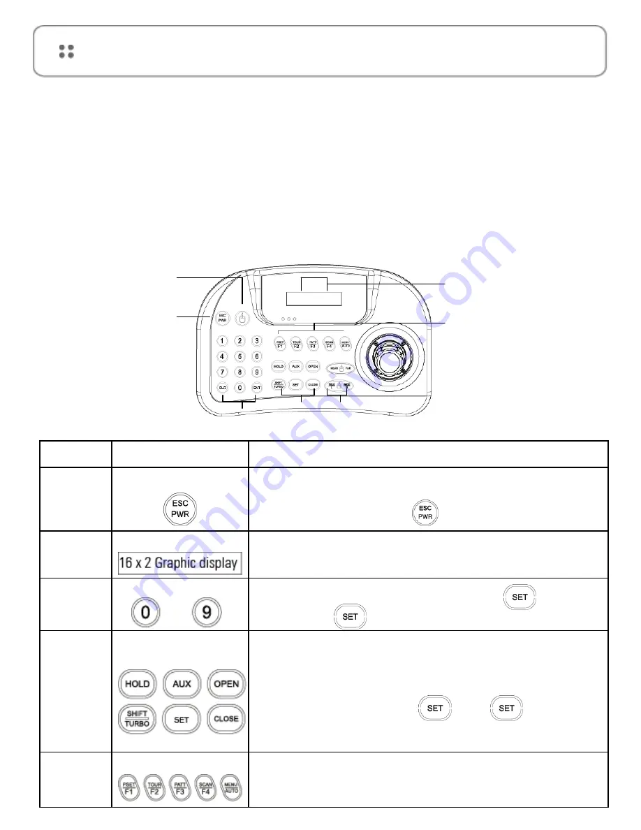
Hardware Components - This remote keyboard contains easy to use control keys on the 

front and simple input and output connectors on the back

Control Buttons & Connection

The unit provides the primary operator interface. Most 

operations are one or two button presses. 

The following Table contains a description for each buttons 

on the keyboard and port of cable connection. Use Figure 1 

and Figure 2 as a reference.

Number

Button

Description

1

ESC / POWER

Pressing the ESC/POWER button enters the Power on/off or 
escape key. Right description led on(red). Pressing it again exits 
the POWER OFF. (Push the              button (about 2~3 seconds) 
and then POWER OFF)

2

LCD DISPLAY

Displays Camera ID, Protocol, Function status, General status, etc.

3

Number

Camera ID setting value change, PTZ setup(1+               ), 

Main setup(2+              )

4

Controller

Function keys

Hold : System locking (Unlocking : Input the Pass word 4 digit ****)

SHIFT/TURBO : SHIFT-Key for special function (Customize) / 

TURBO -High Speed 

AUX : External equipment on/off

SET : Ptz and main setup (1 +              ), (2+              )

IRES CLOSE : Camera Iris close

IRIS OPEN : Camera Iris open

5

Function keys

F1 ~ MENU/AUTO : Function Keys 

(Preset, Tour, Pattern, Scan, Auto).

MENU :Used for Camera (Pan/Tilt) Menu adjustment.

1

2

3

4

5

6

7

< Figure 1 >

User Manual - ASTKJ-1201P - AASSET SECURITY

Summary of Contents for ASTKJ-1201P

Page 1: ...ASTKJ 1201P keyboard...

Page 2: ...w 08 System Configuration and Wiring 10 CHAPTER 2 SYSTEM INSTALLATION TYPICAL APPLICATIONS System Installation 11 PTZ SETUP 11 MAIN SETUP 12 JOYSTICK CALIBRATION 13 EASY SETTING FUNCTION E S F 14 SPEC...

Page 3: ...PECTS HOWEVER WE CANNOT ASSUME RESPONSIBILITY FOR ANY CONSEQUENCES RESULTING FROM THE USE THERE OF THE INFORMATION CONTAINED HEREIN IS SUBJECT TO CHANGE WITHOUT NOTICE REVISIONS OR NEW EDITIONS TO THI...

Page 4: ...OCK DO NOT REMOVE COVER OR BACK NO USER SERVICEABLE PARTS INSIDE REFER SERVICING TO QUALIFIED SERVICE PERSONNEL CAUTION RISK OF ELECTRIC SHOCK DO NOT OPEN The lightning flash with arrow head symbol wi...

Page 5: ...does not have the grounding plug receptacle contact your local electrician 9 CORD AND CABLE PROTECTION Route power cords and cables in a manner to protect them from damage by being walked on or pinche...

Page 6: ...E HARMFUL INTERFERENCE TO RADIO COMMUNICATIONS OPERATION OF THIS EQUIPMENT IN A RESIDENTIAL AREA IS LIKELY TO CAUSE HARMFUL INTERFERENCE IN WHICH CASE THE USER WILL BE REQUIRED TO CORRECT THE INTERFER...

Page 7: ...port of PC Built in 2 lines character LCD User password support Designed for desktop use programmable transmission speed for each ID 2 4 57 6kbps Note units should be set to the communication protcol...

Page 8: ...on off or escape key Right description led on red Pressing it again exits the POWER OFF Push the button about 2 3 seconds and then POWER OFF 2 LCD DISPLAY Displays Camera ID Protocol Function status G...

Page 9: ...ft button of Computer mouse Right button of Computer mouse Scroll key of Computer mouse Middle key Simultaneously near far key push and joystick move DVR Connection method Push a mouse button KEY Shor...

Page 10: ...Keyboard Configuration when only one keyboard is connected to the controlled units Connect the RS 485 output port of Remote keyboard to RS 485 input port of the first controlled unit using the termin...

Page 11: ...s working correctly Before use of this keyboard you should set the protocol and baud rate 2 4 57 6kbps in the PTZ SETUP mode Use the following steps to set the communication protocol and baud rate PTZ...

Page 12: ...ONS MAIN SETUP MAIN SETUP Main Setup mode select 2 2 3 seconds setup screen allows you to make change ench programmable clause Note The baud rate must be the same between the controlled unit and the k...

Page 13: ...CHAPTER 2 SYSTEM INSTALLATION TYPICAL APPLICATIONS JOYSTICK CALIBRATION User Manual ASTKJ 1201P AASSET SECURITY...

Page 14: ...SETTING FUNCTION E S F MAIN SETUP Main Setup mode select 2 2 3 seconds setup screen allows you to make change ench programmable clause Note The baud rate must be the same between the controlled unit a...

Page 15: ...button Numeric keypad and camera function key Joystick Stick 3 axis variable speed with zoom Input Valtage 12V DC 9V batt Safe mode Power Consumption Max 140mA LCD Display Graphic display 16 2 Graphic...

Page 16: ...key to escape from the current menu N A Toggles between the different view modes eg fisheye quadview Panorama etc NEAR Camera Focus Control Toggles between which VCAM view is being controlled when in...

Page 17: ...User Manual ASTKJ 1201P AASSET SECURITY...

Page 18: ......

Reviews: