Ascotel® IntelliGate® 150/300 as of I7.9
Installation
121
sy
d-
021
0/1.
7
– I7.
9 – 1
2.
2009
Combining Ethernet and AD2 interfaces
1)
LAN switch modules can be combined with AD2 terminal cards. In this case the
LAN switch module assumes the function of two wiring adapters and routes the
AD2 interfaces together with the Ethernet interfaces to the same RJ45 sockets on
the front panel. The same thing is also possible with the AD2 interfaces of the
mainboard if the slots WA0 and WA1 are used for the LAN switch module. This
means that universal building cables can be used simultaneously for data and
voice transmission. The signals are separated again at the cable extremity and
routed to separate connection sockets.
Tab. 55
Connection of Ethernet/AD2 interfaces
Terminal cabling
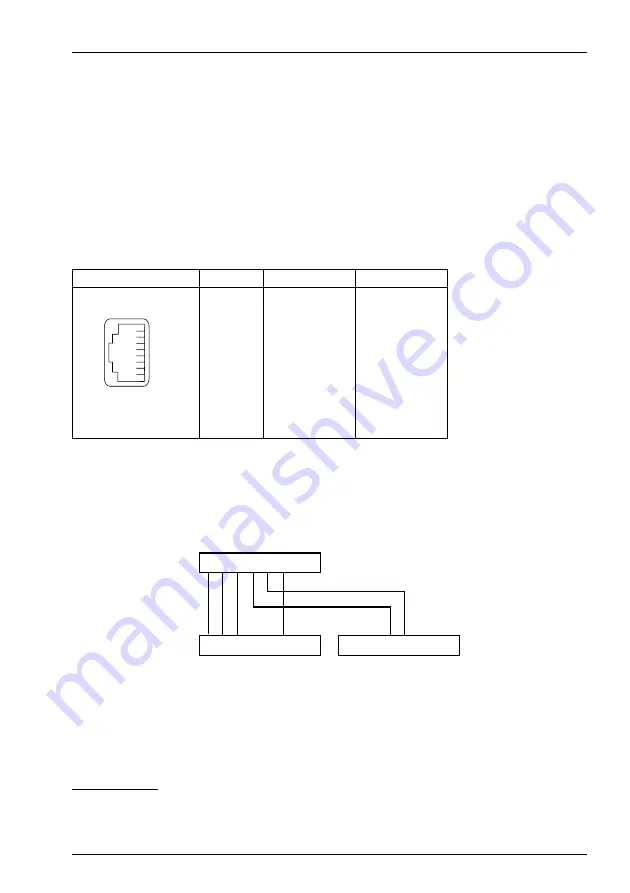
At the cable extremity the signals are separated as indicated in the diagram below
and wired to two connection sockets.
Fig. 62
Connection diagram
1)
Not allowed in Australia
RJ45 socket
Pin
Signal
Interface
1
Tx+
Ethernet
2
Tx–
Ethernet
3
Rx+
Ethernet
4
a
AD2
5
b
AD2
6
Rx–
Ethernet
7
—
—
8
—
—
TOTHE,!.TERMINAL
TOTHE2*CONNECTORSTRIP
TOTHE!$TERMINAL


