Ascotel® IntelliGate® 150/300 as of I7.9
26
Expansion Stages and System Limits
sy
d-
021
0/1.
7
– I7.
9 – 1
2.
2009
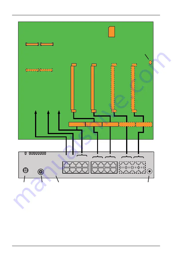
Legend:
IC1...IC4
Slots for interface cards (trunk cards, terminal cards and options cards)
WA0...WA4Slots for Wiring Adapter and LAN switch modules
SM1
Slot for stackable system modules, type 1 (DSP modules)
SM2
Slot for stackable system modules, type 2 (for future expansions)
Fig. 8
Mainboard and front panel interfaces
(A300)
EIM card holder
IC4
(A300)
(A300)
(A300)
IC3
(A300)
IC2
EIM
IC1
SM1
SM2
Audio
input
Supply
input
LED display
Front
panel
Prog. button
WA0
WA1
WA2
WA3
WA4
FAN
(A300)
Mainboard
Connector
for fan
Interfaces internal
a/b
Ethernet
AD2
LINK /
LAN
AD2
0.7
AD2
0.5
a/b
0.3
1.1
1.3
2.1
2.3
3.1
3.3
4.1
4.3
1.2
1.4
2.2
2.4
3.2
3.4
4.2
4.4
0.8
0.6
0.4
SYS
F4
F3
F2
F1
F0
LAN
AUX
PWR
PWR
AUDIO
CTRL
AD2
a/b
LAN
AD2
(A300)


